
Sump pump backup power
A sump pump is not a steady appliance load. It is a motor that must start reliably, move water faster than the pit fills, cycle through the worst part of a storm, and continue after utility power fails. A strong plan therefore needs both electrical capacity and hydraulic capacity. It also needs a second failure path, because a battery that powers the existing pump cannot rescue a jammed pump, failed float, blocked pipe, or overwhelmed basin.

For serious flood risk, use a separate backup pump, not only a larger battery.
The most resilient residential arrangement is an AC primary pump plus a separate DC backup pump with its own higher float, check valve, compatible battery, charger, and high-water alarm. This protects against a utility outage and can also respond when the primary float or pump fails. A portable power station can be useful when it is proven to start the AC motor and is kept dry, but it still depends on the same primary pump. A generator can extend runtime during a long outage, while a layered system combines automatic battery response with a planned recovery source.
Do not choose from horsepower or battery watt-hours alone. Record the pump's voltage, running watts, highest startup demand, flow at actual total dynamic head, run seconds per cycle, starts per hour during heavy rain, and the outage duration you want to cover. Then add reserve and test the complete system under controlled conditions before storm season.
Dedicated DC backup pump
A second pump, float, battery, controller, and alarm can respond to both lost power and primary-pump failure.
Plan the second pumpPortable battery system
Runs the existing AC pump only after the inverter, startup, transfer, location, and runtime tests are passed.
Check the AC routeGenerator or hybrid
Adds fuel-based recovery for multi-day storms, with strict outdoor placement and a safe connection method.
Plan recoveryWater-powered backup
Can operate without a battery when municipal pressure, plumbing rules, water capacity, and discharge conditions allow it.
Check suitabilityStart with the consequence
Sump backup is a property-protection system, not just another appliance calculation
A refrigerator can coast for a period with its door closed. A sump pit may not. When heavy rain, saturated soil, a high water table, and a grid outage occur together, water can continue entering the basin every minute. The load stops when inflow falls, not when the household decides to conserve energy. That makes pump capacity, automatic response, and fault detection as important as stored watt-hours.
The backup must pass two independent tests. First, the power source must start and run the motor at the pump's required voltage. Second, the active pump must move more water than the site delivers at the actual discharge head. A large battery connected to an undersized pump still loses the hydraulic race. A powerful pump connected to an inverter that trips on startup never begins that race.
Electrical start and energy
The source supplies the motor's highest startup demand, continuous running power, correct voltage and waveform, plus enough usable energy for the storm duty cycle.
Water removal at the site
The pump curve at total dynamic head exceeds measured peak inflow, while the basin, float travel, check valve, pipe, outlet, and discharge route all remain clear.
There is also a third question: what happens when one component fails? A portable power station addresses a loss of utility power, but normally retains the original pump, float, check valve, and discharge path. A separate backup pump adds real mechanical redundancy. The best choice depends on flood consequence, site inflow, outage history, ability to test, and whether anyone will be home to intervene.
Four measurements
Measure the installed system before choosing backup equipment
The motor's horsepower is useful for identifying the pump, but it is not a reliable inverter or battery specification. Pumps with similar horsepower can have different current, startup behavior, efficiency, switching, and performance curves. Begin with the exact model and manual. Photograph the pump label, controller, receptacle, discharge route, check valve, and basin layout so a plumber or electrician can review the same system you are sizing.
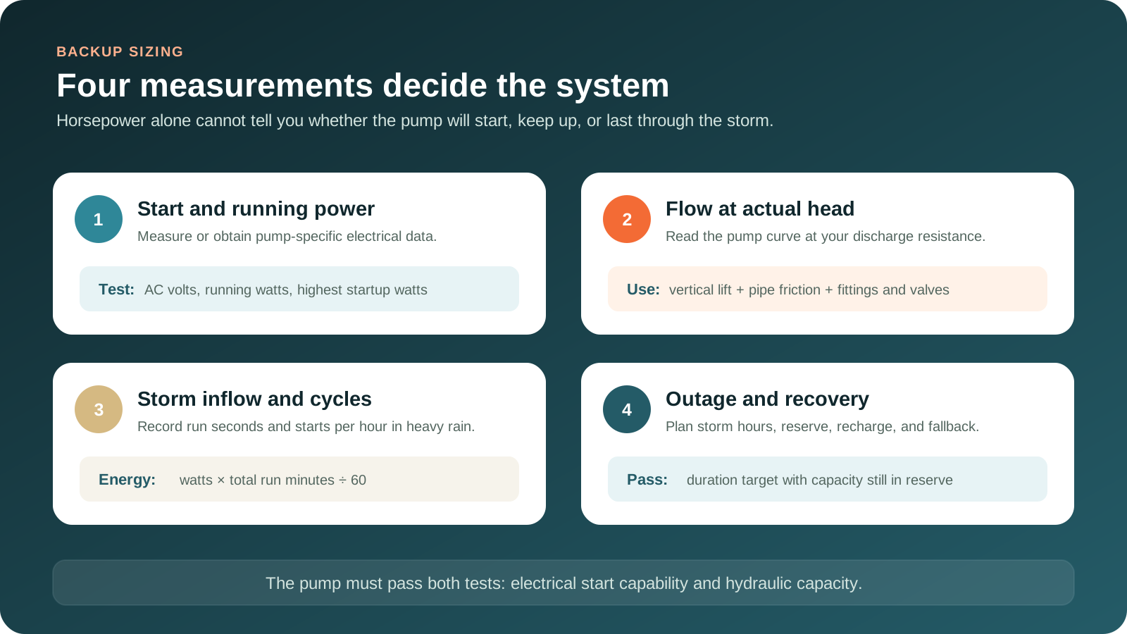
Create a pump data record
Use manufacturer data and qualified measurement where needed. Capture the highest real demand, not only a calm-weather observation.
- Electrical supplyVoltage and circuit
- Normal operationRunning watts or amps
- Motor startHighest startup watts or amps
- Hydraulic outputGPM at actual TDH
- Storm behaviorSeconds per run and starts per hour
How to obtain startup demand
Prefer the pump manufacturer's electrical data or a qualified electrician's inrush measurement. A simple plug-in energy meter may report running power but miss a brief startup peak. If neither source is available, do not treat a generic multiplier as proof. Choose equipment with a documented motor-start capability and complete a controlled start test.
If water is already present near receptacles, cords, controls, or the service panel, keep out of the area and have power isolated from a dry, safe location by the appropriate professional or utility. Testing belongs in a dry, controlled condition.
Pump curve, not box maximum
Verify gallons per minute at total dynamic head
A pump's maximum flow is usually measured at very low resistance. Your installed flow is lower because water must rise vertically, travel through pipe, pass fittings and check valves, and exit at a permitted location. Total dynamic head combines static lift with friction and operating resistance. The correct design point is where the installed system meets the pump curve, not the largest number printed in marketing material.
Water level to outlet high point
Measure the vertical rise the pump must overcome. Do not substitute basement ceiling height without tracing the real path.
Length, diameter, and material
Long runs and undersized piping increase friction. Use the pipe arrangement and sizing method required for the installed pump.
Every restriction matters
Elbows, transitions, check valves, and outlet conditions add resistance and can change delivered flow.
The water entering the pit
The active pump must remove water faster than the worst credible inflow, with margin for aging, debris, and changing conditions.
Use the exact manufacturer's curve for both the primary and backup pump. A dedicated 12-volt backup pump may have lower flow than the AC primary, especially as head rises or battery voltage falls. That does not automatically make it unsuitable, but it must still keep pace with the site's measured or professionally estimated peak inflow. If it cannot, select a higher-capacity architecture, reduce system resistance where permitted, or add a properly engineered second path.
Check valves prevent discharged water from falling back into the basin and forcing repeated cycles. When primary and backup pumps share a discharge, the arrangement must follow the system manual and local plumbing requirements. Some combination systems use separate check valves before a common connection. An incorrect shared connection can let one pump push water backward through the other path.
Continuous operation can mean inflow is near pump capacity, the discharge is restricted, the check valve is leaking, the float is stuck, or the pump is failing. Investigate the hydraulic cause. Adding battery capacity without correcting the water-handling problem can delay, but not prevent, overflow.
Convert cycling into energy
Record how the pump behaves during the rain that matters
Battery runtime depends on total motor run time, not simply elapsed outage time. A pump that runs for 30 seconds every ten minutes uses far less energy than the same pump running for 45 seconds every two minutes. Conditions can also intensify after the grid fails, so a fair measurement should capture a heavy-rain period and include reserve for a worse segment of the storm.
Use a dry, safe observation point. Record the time each run begins, the run duration, and the number of starts per hour. A high-water or pump-monitoring controller may provide better data without requiring someone to remain in the basement. Repeat the observation across more than one storm if possible. Ground saturation, frozen soil, snowmelt, blocked drainage, and nearby construction can change inflow.
Cycle seconds × starts
Run min/h = seconds per cycle × starts per hour ÷ 60
Example: 30 seconds × 20 starts ÷ 60 = 10 run minutes per hour.
Watts across run time
Wh = running W × run minutes ÷ 60
A 720-watt pump running ten minutes uses about 120 watt-hours that hour.
Hourly use across duration
Storm Wh = average Wh/h × outage hours
Model the intense period separately instead of averaging it away across a quiet day.
Frequent short cycling can also stress the motor and starting components. The right response may involve basin volume, float range, check-valve behavior, or pump selection, not merely a larger power source. Follow the installed pump's duty guidance and have abnormal cycling reviewed by a pump professional.
Runtime math
Size stored energy from measured pump run time
For an AC pump powered through an inverter, begin with energy actually delivered to the pump. Then allow for conversion losses, the battery's usable operating range, temperature, aging, controller consumption, and a deliberate reserve. The planning factor must match the equipment. A conservative illustration can use 85 percent delivered energy and then retain a 25 percent reserve, but the product's tested behavior and manufacturer specifications should replace this generic assumption.
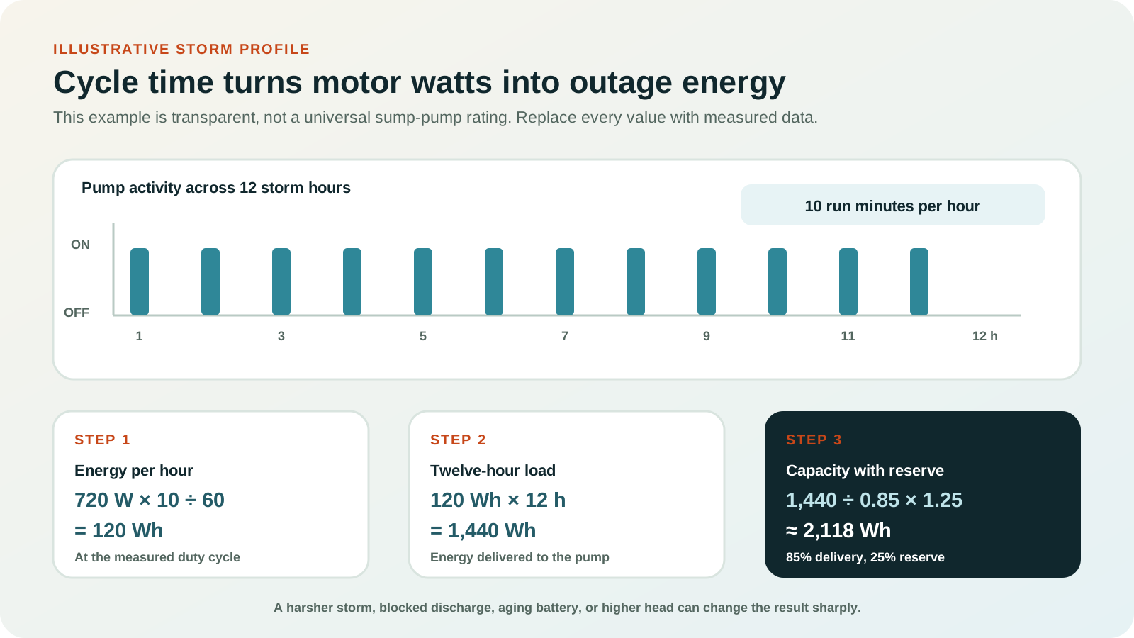
A 720-watt pump running ten minutes per hour uses 120 Wh per hour. Across a 12-hour storm segment, that is 1,440 Wh delivered to the pump. Dividing by 0.85 for delivery and multiplying by 1.25 for reserve gives about 2,118 Wh. This does not prove the inverter can start the motor, and it does not cover other household loads.
Do not count the same reserve twice, and do not hide assumptions. If the power source also runs a refrigerator, freezer, communications equipment, lights, or a furnace, add their energy and simultaneous output to the system model. A property-protection load deserves a protected allocation. Load shedding should prevent discretionary appliances from consuming the energy reserved for the sump pump.
A dedicated DC backup system is sized differently. Use the backup pump manufacturer's stated pumping performance and battery compatibility, then evaluate runtime at your head and expected duty. Battery amp-hours alone are not comparable across systems without voltage, discharge rate, usable range, controller behavior, and pump load. Use the battery type and capacity approved for the controller. Substituting chemistry or capacity without confirmation can produce incorrect charging, unreliable alarms, or reduced runtime.
Model the pump and every shared load
Enter measured running watts and realistic storm run time, then keep startup capability as a separate pass/fail check.
Choose the architecture
Compare what each backup route can and cannot protect
| Backup route | Responds automatically | Survives primary pump failure | Runtime model | Main limitation | Best fit |
|---|---|---|---|---|---|
| Dedicated DC backup pump | Normally yes, through its own float and controller. | Yes, when it has a separate pump and functional discharge path. | Compatible battery, pump flow, head, and cycle rate. | Backup flow may be below the primary and batteries require maintenance. | Automatic first response and mechanical redundancy. |
| Portable battery with AC output | Only if the connection and transfer behavior are designed and tested for it. | No. It normally powers the same pump and float. | Watt-hours, inverter delivery, pump duty cycle, and reserve. | Motor startup, transfer delay, wet-location placement, and single-pump dependency. | Flexible power for a verified AC pump and other selected loads. |
| Installed home battery | Often, when the sump circuit is on backed-up loads. | No, unless a separate backup pump is also installed. | Whole-system kWh, reserved load, solar recovery, and outage policy. | Other household loads can consume the sump reserve. | Automatic circuit backup with load management. |
| Portable or standby generator | Portable is usually manual; standby can be automatic. | No, unless it powers a separate pump or the primary remains healthy. | Fuel, load, maintenance, refueling, and safe operating windows. | Carbon monoxide, weather, fuel, noise, connection, and startup readiness. | Long outage support and battery recharging. |
| Water-powered backup pump | Can be automatic through its own float and valve. | Yes, with a separate water-powered pump and available supply pressure. | Municipal pressure, water consumption, lift, and inflow. | Not suitable for every water service, code, pressure, well, or discharge condition. | Site-qualified backup without stored electricity or fuel. |
No single row is universally best. High-consequence homes often layer an automatic dedicated backup pump with an alarm, then retain a generator or larger battery as a recovery source. The automatic layer buys response time. The recovery layer extends operation. The alarm tells someone that the first layer has changed state.
Independent second line
Why a dedicated backup pump is the strongest default
A dedicated backup system places a second pump in or beside the basin, activates it from a separate float set above the normal primary level, and powers it from a matched battery and controller. If utility power fails, the DC pump can operate. If the primary float sticks or the AC pump stops, rising water can still trigger the second float. A combination system may arrive with the pumps, valves, and plumbing arrangement already matched, while retrofit systems require careful fit and discharge planning.
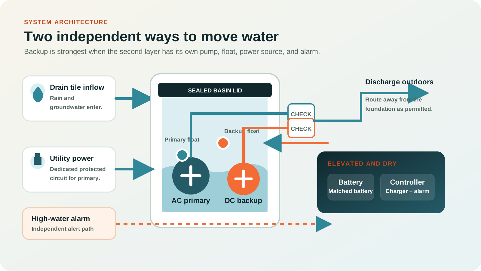
The basin must support two pumps
Both floats need unobstructed movement. Crowding, pipe placement, cords, or a small basin can prevent reliable activation.
The backup must keep up
Compare backup pump performance at the installed head with credible peak inflow, not with the primary pump's horsepower.
Use an approved combination
Follow the controller manual for battery chemistry, capacity, ventilation, enclosure, charger, terminals, alarms, and replacement.
Place the battery, charger, alarm, and electrical connections above the anticipated water level and where the manufacturer permits. Keep them accessible for inspection without requiring someone to reach over an open pit. A fitted basin lid reduces debris, odor, humidity, and accidental contact, while proper pipe penetrations preserve service access.
The higher backup float should trigger before the basin overflows but after the primary pump's normal operating range. The alarm should sound or send a remote message when the backup activates, power fails, battery condition changes, or water rises too high. An alert is valuable only if someone receives it and knows the response plan.
AC power station route
A portable battery can work, but it needs five proofs
A portable power station can run some 120-volt sump pumps and provide useful capacity for other critical loads. It is not a drop-in guarantee. The unit must start the motor repeatedly, sustain running watts, tolerate the pump's power factor and waveform needs, remain connected or transfer quickly enough for automatic operation, and stay safely above any water exposure.
- 1Prove startup
Confirm the inverter's documented surge behavior with motor loads, then run repeated controlled starts. A successful start once is not the same as reliable cycling through a storm.
- 2Prove automatic behavior
If the battery is expected to sit between the wall and pump, verify pass-through, outage transfer, grounding, GFCI behavior, charging, and restart behavior with both manufacturers and a qualified electrician.
- 3Protect the energy reserve
Allocate pump capacity first. Prevent cooking, heating, cooling, or other discretionary loads from draining the reserve during the storm.
- 4Protect the equipment from water
Locate the battery and every connection in a dry position above credible flood exposure, within temperature and ventilation limits, with no cord lying where water may collect.
- 5Keep mechanical redundancy
Add a separate high-water alarm and consider a second pump. The power station does not correct a failed primary pump, float, check valve, or pipe.
Do not assume a computer UPS is suitable. Many units are designed for electronics, not high-inrush motors or long cycling. Some have a stepped waveform, limited overload time, small batteries, or behavior that changes when utility power disappears. Use only equipment whose output, environment, and connection are appropriate for the pump, then test the exact combination.
For a larger battery shared with the home, place the sump pump in the highest load-priority tier. Installed systems can back up the dedicated pump circuit automatically, but commissioning should verify that 240-volt loads or high-power appliances cannot consume the capacity reserved for water removal.
Start with motor capability, not marketing capacity
Use the buyer guide after you know startup watts, running watts, voltage, and the storm energy target.
Long-outage recovery
Use a generator to extend duration, not as an excuse to skip automatic backup
Storms can disable power for longer than a practical battery-only design. A generator can run the pump, support selected home circuits, or recharge a compatible battery system. The gap is response time. A portable generator may not be deployed when nobody is home, while rain, wind, darkness, flooding, or unsafe outdoor conditions can delay setup. A dedicated battery backup pump bridges that gap automatically.
A hybrid sequence can be more efficient and resilient: the battery pump or home battery responds immediately and runs quietly; a generator operates later in safe windows to carry loads or recharge; stored energy resumes overnight or while the generator is off. This reduces continuous engine runtime and creates a reserve for a failed start or temporary fuel interruption.
Automatic battery response
The dedicated backup pump or backed-up circuit starts without waiting for manual deployment.
Safe generator operation
The generator carries selected loads or recharges compatible storage from a documented connection path.
Return to stored energy
The battery retains enough charge to cover refueling, shutdown, sleep hours, or another generator fault.
Size the generator for the pump's startup plus every load expected to be on at that moment. A refrigerator, freezer, furnace blower, or well pump can create overlapping motor starts. Use load management or a deliberate operating schedule to avoid stacking starts. If connecting to household wiring, use properly installed transfer equipment that prevents backfeed. Never improvise a connection through a receptacle.
Portable generators must operate outdoors only, at least 20 feet from the home and other buildings, with exhaust directed away from windows, doors, vents, and occupied areas. A garage, basement, crawlspace, porch, or carport is not safe, even with doors open. Follow the generator manufacturer's wet-weather instructions and keep electrical operation away from standing water.
Combine automatic response with controlled recovery
Model charging compatibility, reserve thresholds, fuel, transfer, and the fallback if either source fails.
No stored electricity
Water-powered backup is useful only when the site qualifies
A water-powered backup pump uses municipal water pressure to create suction and remove sump water. It can activate through its own float without a battery or fuel supply. That sounds simple, but suitability depends on stable municipal pressure during an outage, service-line capacity, local plumbing rules, approved backflow protection, lift, discharge routing, and the amount of potable water consumed for each amount pumped.
It is generally not a solution for a home whose water comes from an electric well pump, because the pressure source may disappear with grid power. It may also be restricted or impractical where drought rules, water costs, backflow requirements, low pressure, private septic constraints, or local codes conflict with the installation. Performance must be evaluated at the home's available pressure and actual head.
Use a licensed plumber familiar with local requirements. Verify how the unit is isolated from potable water, how the discharge is routed, how it is tested, and whether a high-water alarm remains available. A water-powered pump can be a valuable independent layer, but it should be selected from measured site conditions, not from the idea that municipal water always continues through every emergency.
Make the whole path reliable
The connection, basin, alarm, and discharge are part of the backup system
Reliable backup is more than a power source beside a pit. The installation begins where water enters the basin and ends where discharge leaves the property. A plumber should verify basin volume, pump fit, float clearance, check valves, pipe support, weep-hole or air-lock provisions where required, discharge freeze protection, and outlet location. An electrician should verify the circuit, receptacle, grounding, GFCI requirements, transfer method, equipment listing, and dry placement.
| System point | What to verify | Why it matters |
|---|---|---|
| Basin and lid | Size, depth, pump spacing, float travel, fitted cover, and service access. | Crowding and debris can block switches or shorten cycles. |
| Primary circuit | Correct voltage, dedicated or required circuit arrangement, protected receptacle, and dry access. | The pump must start without nuisance trips or unsafe cord routing. |
| Backup battery | Approved type, charger, enclosure, ventilation, elevated location, terminals, and temperature range. | Battery condition and charging directly control automatic runtime. |
| Check valves | Correct orientation, independent paths where required, accessibility, and leak-free operation. | Backflow can cause repeated cycling or defeat the inactive path. |
| Discharge | Head, pipe condition, freeze exposure, obstruction, legal outlet, and drainage away from the foundation. | A working motor cannot overcome a blocked or recirculating discharge. |
| Alarm and communications | High-water, power-failure, pump-run, battery-fault, local sound, and remote notification. | Early warning can prevent a single fault from becoming an unnoticed flood. |
Avoid ordinary extension cords unless the pump manufacturer and electrical requirements explicitly permit the exact arrangement. Keep plugs, adapters, controllers, and portable batteries off the floor and outside the anticipated water zone. Do not place a power station on a shelf that blocks ventilation or exposes it to condensation. Never connect a generator or inverter to home wiring without an approved transfer method.
Design around faults
Ask what survives when one component stops working
Grid is lost
Dedicated battery backup, a backed-up circuit, standby generation, or qualified water-powered backup can respond.
Motor or impeller stops
A separate backup pump can respond. A battery powering the same failed motor cannot.
Float sticks or tangles
An independent higher float and alarm provide a second trigger and warning path.
Pipe blocks or inflow wins
Alarm, separate discharge design, inspection, and correctly sized flow are required. More battery alone is not enough.
Extend the exercise to every common fault: depleted or aging battery, failed charger, unplugged transformer, tripped breaker, stuck check valve, frozen outlet, disconnected pipe, blocked intake, failed remote network, generator that will not start, unavailable fuel, and storm conditions that prevent safe deployment. Give each fault a detection method and a response.
Remote monitoring should not depend only on the home's Wi-Fi if the router loses power. Back up the modem, router, fiber terminal, and any monitoring hub, or use a controller with its own communications path where appropriate. Make sure alerts identify the event clearly. "Power failed," "backup pump running," and "high water" require different urgency.
Confidence comes from testing
Test the full sequence before the storm, then maintain every layer
Follow the pump and controller manuals for test frequency and exact procedure. A useful test verifies more than motor noise. It confirms the primary float starts the primary pump, the water level falls, the check valve holds, the backup float activates the second pump, the alarm sounds, the battery state is acceptable, and water exits at the correct outdoor location. Use the controller's self-test function where provided.
- 1Inspect the dry system
Check the basin lid, pump position, float clearance, cords, pipe supports, valves, battery enclosure, charger lights, alarm, and discharge outlet.
- 2Run the primary pump
Introduce water only by the method permitted for the system. Observe activation, flow, shutdown, backflow, vibration, unusual sound, and cycle time.
- 3Run the backup procedure
Use the manufacturer's power-failure or controller test procedure. Verify the backup pump, higher float, alarm, and battery indication without reaching into energized water.
- 4Verify the alert path
Confirm local sound and remote notifications reach the intended people while the communications equipment is on backup power.
- 5Record and correct
Log the date, run behavior, battery status, issues, repairs, and next service. Investigate changed cycle frequency or weaker flow.
Maintain the battery exactly as its manufacturer requires. Record installation date and replacement guidance. Inspect terminals for corrosion or looseness without bypassing safety procedures. A charger light may show charging status but not prove the battery can deliver pump current under load, so use the controller's diagnostic or a qualified load test when specified.
Inspect after major storms and before seasons when outages and heavy rain overlap. Keep the outdoor discharge clear of leaves, ice, snow, landscaping, pests, and damage. Correct a noisy or leaking check valve, short cycling, repeated alarm, or continuous run before the next event. A system that passed years ago is not automatically ready today.
Transparent examples
Three household profiles show why duty cycle changes the answer
These profiles are calculation examples, not product recommendations. Each AC example uses measured running watts, a measured storm duty cycle, 85 percent delivered-energy planning, and a 25 percent reserve. Startup capability, hydraulic capacity, battery environment, and connection still require separate verification.
Moderate inflow, short outage
- 600 W running
- 1,800 W measured startup
- 20 seconds every 10 minutes
- 12-hour target
- Run time
- 2 min/hour
- Pump energy
- 240 Wh
- Planned capacity
- About 353 Wh
The energy is modest, but the source still must start the motor and remain automatic. A separate backup pump may offer more fault protection than capacity alone.
Active storm cycling
- 720 W running
- 2,160 W measured startup
- 30 seconds every 3 minutes
- 12-hour target
- Run time
- 10 min/hour
- Pump energy
- 1,440 Wh
- Planned capacity
- About 2,118 Wh
This profile needs a much larger reserve. Other home loads must be controlled, and long-outage recovery becomes important.
High inflow, high consequence
- 900 W running
- 2,700 W measured startup
- 45 seconds every 2 minutes
- 12-hour target
- Run time
- 22.5 min/hour
- Pump energy
- 4,050 Wh
- Planned capacity
- About 5,956 Wh
The system is nearing a serious duty level. Hydraulic review, a second pump, alarm, and generator or other recovery path matter as much as battery size.
Profile 1 calculation: 600 W × 2 minutes per hour ÷ 60 × 12 hours = 240 Wh. Then 240 ÷ 0.85 × 1.25 = about 353 Wh. Profile 3 calculation: 900 W × 22.5 ÷ 60 × 12 = 4,050 Wh. Then 4,050 ÷ 0.85 × 1.25 = about 5,956 Wh. The arithmetic is straightforward. The difficult work is obtaining a credible storm duty cycle and confirming the pump can keep up.
Non-negotiable boundaries
Water, electricity, and generator exhaust require strict separation
If a basement floor is wet near electrical equipment, do not enter the water to inspect the pump, unplug equipment, or reach the service panel. Have power shut off from a dry, safe location. Equipment that has been submerged or exposed to floodwater requires professional evaluation before reuse.
Stay out. Do not touch cords, pumps, receptacles, batteries, or panels while standing in water or on a wet surface.
Operate outdoors only, at least 20 feet from structures, with exhaust directed away from doors, windows, vents, and occupied areas.
Use approved transfer equipment for household wiring. Never energize a home by improvising a generator or inverter connection through a receptacle.
Use the approved battery and enclosure, maintain required ventilation and temperature, protect terminals, and keep the system above credible water exposure.
Follow the pump, backup, inverter, and local electrical requirements. Do not bypass protective devices to stop nuisance tripping.
A sump pump does not make a building safe during rising external floodwater. Follow official warnings and leave when authorities direct evacuation.
Installer handoff
Use this checklist before relying on the system
- Exact pump identifiedModel, voltage, running demand, startup demand, and manual are recorded.
- Hydraulic design verifiedActual head, pump curve, pipe, valves, outlet, and peak inflow are reviewed.
- Storm duty measuredRun seconds, starts per hour, and intense-storm duration are documented.
- Backup path independentSecond pump, float, power, check valve, and alarm are installed where risk justifies them.
- Stored energy calculatedDelivery losses, battery limits, temperature, aging, other loads, and reserve are visible.
- Equipment stays dryBattery, controller, receptacles, connections, and portable power are above the planned water zone.
- Recovery source is readyGenerator, installed battery, solar, or other recovery has a documented compatible path.
- Alerts reach someoneHigh water, outage, battery fault, and pump operation are tested locally and remotely.
- Whole sequence testedPrimary, backup, alarm, check valves, discharge, battery status, and restart all pass.
- Response plan is writtenContacts, shutoff boundary, generator procedure, service provider, and evacuation triggers are known.
Common questions
Sump pump backup questions
Can a portable power station run a sump pump?
Yes, some can, but only when the AC output repeatedly starts the exact motor, sustains running watts, provides enough stored energy for the measured duty cycle, transfers or reconnects as required, and can be installed in a dry, safe location. It still depends on the existing pump and float.
How many watts does a sump pump need?
There is no safe universal number. Identify the exact model and obtain running plus startup demand from manufacturer data or qualified measurement. Horsepower and running watts alone do not prove inverter start capability.
Is a battery backup pump better than powering the main pump?
For mechanical redundancy, usually yes. A separate battery-powered pump with its own float can operate when the primary pump or float fails. Powering the main pump may offer more flow and flexible energy, but it retains the same mechanical failure points. High-risk homes often use both concepts in layers.
How long will a battery run a sump pump?
Runtime depends on pump power, seconds per cycle, starts per hour, total head, inflow, battery delivery, temperature, age, and reserve. Calculate total motor run minutes during a heavy storm, not merely the outage clock time.
Should the generator be in the garage because it is raining?
No. A portable generator must never operate in a garage, basement, crawlspace, porch, carport, or other enclosed or attached area. Operate it outdoors at least 20 feet from structures with exhaust directed away from openings, and follow manufacturer wet-weather instructions.
What is the most important alarm?
A high-water alarm is essential because it reports the consequence regardless of whether the cause is lost power, pump failure, float failure, blocked discharge, or inflow above capacity. Power, pump-run, and battery-fault alerts add diagnostic value.
Protect the basement with two working paths and one tested response plan
Measure the pump, verify flow at actual head, record severe-storm cycling, calculate stored energy transparently, and keep the power equipment dry. Then add the part capacity cannot replace: an independent backup pump or other qualified second path, plus a high-water alarm and a recovery plan for a long outage.
Technical and safety sources
- Zoeller Pump Company: pump sizing, total dynamic head, and flow
- Zoeller Pump Company: sump pump cycling and run-time considerations
- WAYNE Pumps: primary, backup, and combination sump systems
- WAYNE Pumps: battery backup sump pump installation and safety manual
- U.S. Consumer Product Safety Commission: portable generator CO and fire safety
- OSHA: portable generator electrical, wet-weather, and carbon monoxide safety
- NOAA National Severe Storms Laboratory: flood and flash-flood basics
Reviewed July 26, 2026. Site conditions, codes, pump curves, battery compatibility, and manufacturer instructions control the final design. Use qualified plumbing and electrical professionals where required.