
Well pump backup power
A private well changes the outage plan because electricity is also the home's water supply. The backup source must produce the pump's exact voltage, start its motor through the installed controls, operate safely through transfer equipment, and deliver enough energy for a deliberate water-use plan. A large battery can still fail if it offers only 120 volts to a 240-volt pump. A generator can have enough running watts and still stumble during motor start. The right answer begins at the well-system nameplate, not with a generic horsepower chart.

Back up the exact well system, then reduce how often it must run.
For many homes with a conventional 240-volt submersible pump, the practical routes are a split-phase home battery, a compatible 120/240-volt generator connected through listed transfer equipment, or a hybrid system that uses quiet battery power for routine loads and generator recovery for longer outages. Some shallow-well jet pumps and smaller systems operate at 120 volts, but the nameplate, breaker, controls, and manual must confirm this. Never assume that a standard portable battery outlet can power a well pump.
Record the motor voltage, phase, horsepower, full-load current, control type, highest starting demand, running watts, pressure-switch settings, tank condition, pumping flow, and daily water target. Verify voltage and motor start before calculating watt-hours. Then conserve water, group high-use tasks, protect a potable reserve, and test the complete source-to-pump sequence before relying on it.
Installed split-phase battery
Can back up a 120V or 240V well circuit when output, surge, controls, transfer, capacity, and load priority are verified.
Plan the battery route120/240V generator
Often handles a conventional pump well, but it must meet manufacturer motor-start guidance and use a safe transfer path.
Plan the generator routeHybrid plus stored water
Combines automatic battery response, generator or solar recovery, load control, and a potable reserve for source failure.
Build the layered planPortable power system
Viable only when the unit supplies the pump's exact voltage, proven surge, compatible connection, and enough usable energy.
Check portable suitabilityWater becomes an electrical load
A well pump backup plan must pass electrical, hydraulic, and household tests
A conventional household appliance converts electricity into heat, light, cooling, or motion inside the home. A well system is a chain. The motor lifts water from the pumping level, pushes it through pipe and check valves, overcomes the pressure required at the tank, and feeds any treatment equipment before water reaches a fixture. Electrical backup is useful only if the entire chain remains functional.
The first test is electrical. The source must provide the pump's voltage and phase, tolerate starting current, support the control box or variable-speed drive, and connect through equipment that isolates the home from the utility. The second test is hydraulic. The pump must still deliver useful flow at the actual pumping head and pressure. The third test is operational. The household must decide how many gallons it truly needs and how the pump will be restored, recharged, refueled, or rested through a long outage.
Electrical compatibility
Correct 120V or 240V output, adequate motor-start response, compatible controls, listed transfer equipment, proper grounding, and enough usable energy.
Water delivery and reserve
Real flow at pumping head, a healthy pressure tank, manageable daily demand, protected storage, treatment continuity, and a response if the pump fails.
Well depth by itself is not an energy specification. A pump set deep in a well may operate from a much higher water level. Conversely, a shallower installation can face a significant pressure requirement, pipe loss, or treatment load. Horsepower also does not reveal exact starting behavior. Use the installed model, well log, control information, and qualified measurements.
Know what you own
Identify the pump, motor, controls, circuit, and water system
Start by locating records rather than opening electrical or well equipment. The well log may show construction depth, casing, static water level, pump setting, and production information. Service invoices may identify the pump, motor, control box, pressure switch, pressure tank, treatment equipment, and replacement history. Photograph accessible labels without removing covers or reaching into energized equipment.
| System type | What it usually means for backup | What must be confirmed |
|---|---|---|
| Submersible pump | The pump and motor are down the well. Residential versions commonly use 230/240V, although 115/120V models exist. | Exact voltage, two-wire or three-wire design, control box, full-load current, start requirements, and pump setting. |
| Shallow-well jet pump | The pump is above ground and may be easier to inspect. Some can be configured for 120V or 240V. | Nameplate configuration, priming requirements, suction limits, pressure switch, running current, and startup. |
| Deep-well jet system | Uses above-ground pumping with additional well components and can have distinct priming and performance needs. | Exact model, voltage, ejector arrangement, pressure, flow, and restart procedure. |
| Constant-pressure system | A variable-speed controller changes motor speed to maintain pressure and may alter starting behavior. | Drive input voltage, maximum input power, generator guidance, waveform requirements, fault behavior, and bypass procedure if any. |
| Conventional pressure switch | The pump starts at cut-in pressure and stops at cut-out pressure, filling the tank drawdown between starts. | Switch settings, tank precharge, drawdown, start frequency, control box, and whether the pump short cycles. |
The breaker size is important evidence, but it is not the pump's running watts. A breaker is selected around conductor protection, motor rules, and starting behavior. Likewise, a pressure tank's total shell volume is not the amount of water available between pump cycles. The usable amount is its drawdown at the installed pressure settings and precharge.
If labels are missing, records conflict, the pump trips breakers, pressure has changed, or the system cycles unusually, stop the sizing exercise and have a water-well professional diagnose the system. Backup power should not conceal a failing pressure tank, damaged control, weak pump, leaking check valve, dry-well condition, or deteriorated wiring.
Measure before buying
Four measurements control the backup decision
The goal is a compact system record that an electrician, well contractor, battery installer, or generator dealer can verify. Manufacturer data is the first source. Qualified inrush and running measurements can then confirm how the installed system behaves. Do not open a control box, alter a pressure switch, or clamp energized conductors unless you are trained and authorized to perform that work.
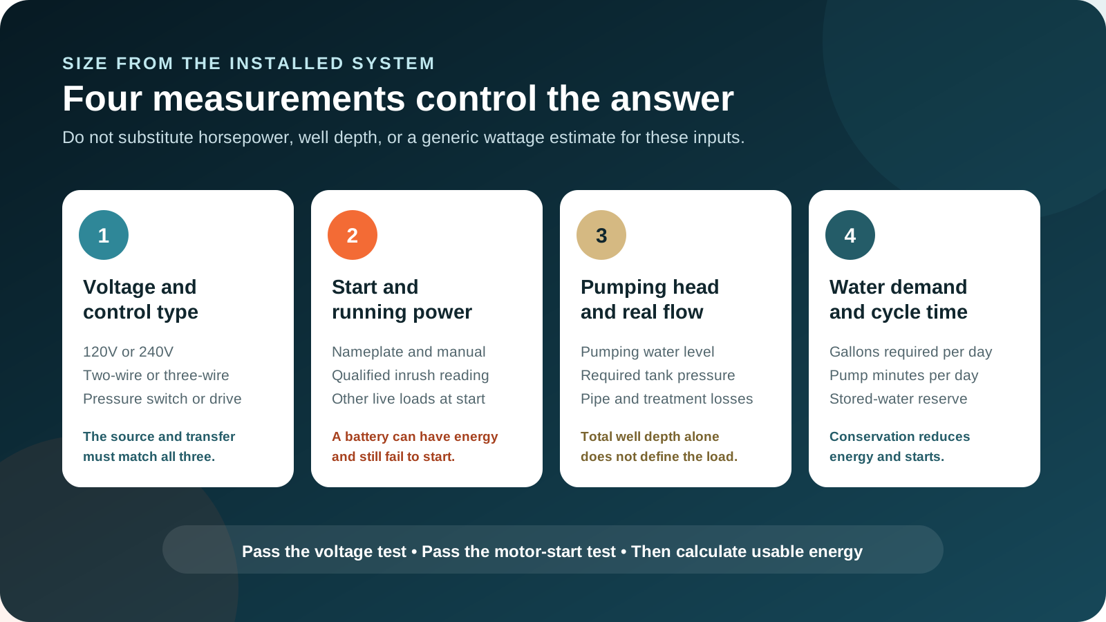
Create a well backup data record
Use exact equipment data and qualified measurements. Keep the record near the transfer procedure and emergency contacts.
- Electrical supplyVoltage, phase, breaker, conductors
- Motor and controlModel, HP, wires, box or drive
- Power demandRunning and highest startup load
- Water deliveryGPM at real head and pressure
- Outage targetGallons, days, reserve, recovery
Where to find the information
Review the motor and pump labels, control manual, well log, service record, pressure-switch settings, tank documentation, pump performance curve, and existing generator instructions. Ask the professionals to record measured voltage, running current, starting current, flow, and observed cycle behavior. Keep photographs of labels and an updated one-line system description.
Both 120V and 240V residential pumps exist, and rewired or dual-voltage equipment may not match a generic product listing. Verify the installed configuration at the motor, controller, breaker, and manual before choosing a source or connection.
Compatibility comes first
Voltage, split phase, wire design, and controls must all agree
A 240-volt well pump generally needs a source that provides the appropriate line-to-line voltage. Two independent 120-volt outlets are not automatically a usable 240-volt supply. A qualified design must address source configuration, overcurrent protection, neutral and grounding requirements, disconnects, transfer isolation, conductor size, inlet rating, and local code. The pump circuit should remain a circuit, not an improvised collection of adapters.
A two-wire submersible motor has its starting components within the motor assembly. A three-wire motor normally uses an above-ground control box. That difference can affect starting behavior, service, and generator sizing. A constant-pressure drive introduces another layer. Its manual may specify input power quality, generator size, grounding, protection, and restart behavior. Follow the exact drive guidance rather than treating it as an ordinary across-the-line motor.
| Compatibility check | Question to answer | Why it matters |
|---|---|---|
| Source voltage | Does the backup source provide the exact input required by the installed circuit and controls? | An energy-rich 120V source cannot directly operate a pump that requires 240V. |
| Output configuration | For 120/240V equipment, does the source and transfer arrangement provide the required split-phase output? | Voltage labels alone do not prove the correct conductor and phase relationship. |
| Control equipment | Is there a control box, soft starter, VFD, constant-pressure controller, contactor, or protective relay? | Controls can change input power, startup, compatibility, fault response, and commissioning. |
| Transfer method | How is the pump isolated from utility power before the backup source energizes it? | Proper isolation prevents dangerous backfeed and conflicting sources. |
| Other required loads | Do water treatment, heat tape, booster pumps, controls, alarms, or pressure equipment also need power? | Running the well pump may not produce usable household water if the rest of the chain is off. |
Installed batteries and generators may support load management. Give the well circuit a high priority, then prevent electric water heating, clothes drying, central air, resistance heat, EV charging, or other large discretionary loads from starting at the same moment. A source can start the pump alone yet trip when another large motor or heating element overlaps.
The short event that decides success
Pass the motor-start test before calculating runtime
Electric motors draw a brief high current while accelerating. The source voltage can dip during this event. An inverter may reach an overload limit, a generator may slow, a control may fault, or the pump may fail to develop enough starting torque. The event can be too brief for a basic energy monitor to capture accurately. Use the equipment manufacturer's data or a qualified inrush measurement.
Do not convert horsepower directly into backup watts. Horsepower describes mechanical output, while the source sees electrical input, losses, power factor, starting current, control behavior, and voltage conditions. Pumps with the same horsepower can require different generators or inverters. Franklin Electric's current AIM resources provide model and motor application guidance, including generator considerations. The final selection should follow the installed motor and control documentation.
- 1Identify the exact motor and control
Record voltage, phase, horsepower, model, wire design, control box or drive, full-load current, and manual.
- 2Establish startup demand
Use manufacturer data or a qualified inrush reading. Record the highest credible start, not only one favorable attempt.
- 3Add overlapping loads
Include the running power of refrigeration, furnace blower, water treatment, communications, and other loads that remain on during pump start.
- 4Check source behavior
Verify voltage stability, frequency where applicable, inverter overload time, generator motor-start guidance, and control compatibility.
- 5Perform a controlled commissioning test
Start the pump through the final transfer path with the planned background loads. Confirm pressure recovery and absence of faults or nuisance trips.
A successful unloaded bench demonstration is not enough. The source should start the actual installed system through its actual wiring and controls. For a battery, repeat the test at a realistically reduced state of charge and within the expected temperature range if the manufacturer permits. For a generator, test after warm-up and with the loads that will remain active during an outage.
Water work, not well depth
Pumping head, pressure, flow, and treatment shape real performance
The motor does work against total head. A simplified residential view includes vertical lift from the pumping water level, the pressure required at the tank or fixtures, and friction through pipe, valves, fittings, filters, softeners, and other treatment. The bottom depth of the well matters for construction and pump setting, but it is not automatically the lift the pump sees while running.
Static water level is the level before pumping. Pumping water level is the level while the well is producing at a given rate. Drawdown is the difference. A low-yield well may experience more drawdown during sustained use, which increases lift and can reduce flow. A professional uses the pump curve and site conditions to confirm gallons per minute at the required head. Backup planning should use that real output, not the pump's best-case catalog flow.
Pumping water level
Use the water level while pumping at the relevant rate, plus the elevation to the pressure system. Do not use total drilled depth as a shortcut.
Tank and fixture target
Household pressure adds head. Higher pressure can change flow, motor load, cycling, and usable pressure-tank drawdown.
Pipe and treatment
Long pipe runs, restrictive filters, valves, fittings, elevation, and treatment can reduce delivered flow and alter pump run time.
Flow also sets the link between gallons and energy. If the installed system delivers 10 gallons per minute and the household plans to use 180 gallons, the pump needs about 18 minutes of run time, assuming that measured flow represents the planned operating conditions. If flow falls to 6 gallons per minute because the water level drops or filters clog, the same volume needs 30 minutes. The source then supplies more energy and the motor stays hot longer.
A buffer, not a multi-day reservoir
The pressure tank reduces starts and provides short drawdown
A conventional bladder or diaphragm tank stores pressurized water so every small faucet use does not start the pump. When system pressure falls to the pressure-switch cut-in setting, the pump starts. It runs until pressure reaches cut-out, replenishing the tank's drawdown. The useful drawdown is only a portion of the tank's total volume and varies with tank size, precharge, and switch settings.
A healthy pressure tank can improve backup operation by making pump cycles longer and less frequent. A waterlogged tank, incorrect precharge, leaking check valve, or faulty pressure switch can cause rapid cycling. Short cycling increases starts, stresses the motor and controls, and repeatedly exposes the backup source to its hardest moment. The National Ground Water Association notes that frequent cycling can point to a malfunctioning pressure tank or pressure switch and recommends professional diagnosis.
| Observation | Possible planning meaning | Appropriate response |
|---|---|---|
| Normal long pump cycle | The tank appears to provide useful drawdown and the pump restores pressure steadily. | Record run time, recovered gallons, pressure range, and electrical demand. |
| Very frequent starts | Tank precharge, bladder, switch, check valve, leak, or system sizing may be wrong. | Have the water system evaluated before sizing or commissioning backup. |
| Pressure falls while pump runs | Demand may exceed pump output, flow may be restricted, or the well may be drawing down. | Review pump performance, filters, leaks, water level, and simultaneous use. |
| Pressure does not hold | A leak or failed check valve may cause unwanted cycling and energy use. | Correct the water-system fault rather than compensating with more battery. |
Do not change pressure-switch settings or tank precharge casually. The pump, tank, switch, relief protection, fixtures, and piping must remain within their ratings. Follow manufacturer procedures, isolate power, depressurize as instructed, and use a qualified well professional where required.
Conservation is energy management
Plan gallons first, then translate them into pump minutes
Trying to preserve normal water habits during an outage can force a much larger power system. Separate essential water from discretionary use. Drinking, basic food preparation, medication, critical hygiene, and sanitation belong in the first tier. Laundry, long showers, outdoor irrigation, vehicle washing, frequent toilet flushing, and filling large tubs can often wait or be reduced.
Ready.gov recommends storing at least one gallon of water per person per day for several days for drinking and sanitation. Treat this as a basic emergency reserve, not a full household-use estimate. People, pets, livestock, medical needs, hot weather, and local conditions can increase the requirement. Store water in appropriate containers, rotate it as recommended, and protect it from contamination and freezing.
| Water tier | Examples | Power strategy |
|---|---|---|
| Tier 1: safe drinking reserve | Stored potable water for drinking, medication, food preparation, and immediate health needs. | Available even if the pump, controls, source, well, or water quality becomes unusable. |
| Tier 2: essential pumped water | Controlled toilet use, brief washing, limited cooking, animals, and critical household sanitation. | Schedule pump windows and monitor daily gallons, source state, and well recovery. |
| Tier 3: deferred demand | Laundry, irrigation, long showers, pressure washing, and other high-volume tasks. | Pause until utility returns or a sustainable recovery source is operating. |
Batching water use can reduce small, repeated pressure-tank cycles. For example, the household can run the pump during planned generator windows, refill an approved potable storage system, complete a short set of essential tasks, then shut down the generator. Any storage tank, booster pump, backflow protection, treatment, disinfection, freeze protection, overflow, and plumbing connection must be designed for potable service and local requirements.
A low-yield well adds another constraint. It may need recovery time between pumping periods. Backup power does not create more groundwater. A pump-protection control, low-water cutout, or drive fault must not be bypassed merely to obtain more water during an outage.
Transparent sizing
Convert gallons to run time, then run time to watt-hours
Once the source passes voltage and startup checks, stored-energy sizing can be straightforward. Divide planned gallons by measured delivered gallons per minute to estimate pump minutes. Multiply running watts by pump hours to estimate pump energy. Then account for conversion losses, battery operating limits, temperature, age, uncertainty, and reserve. Add any treatment, controls, pressure booster, heat trace, and other household loads separately.
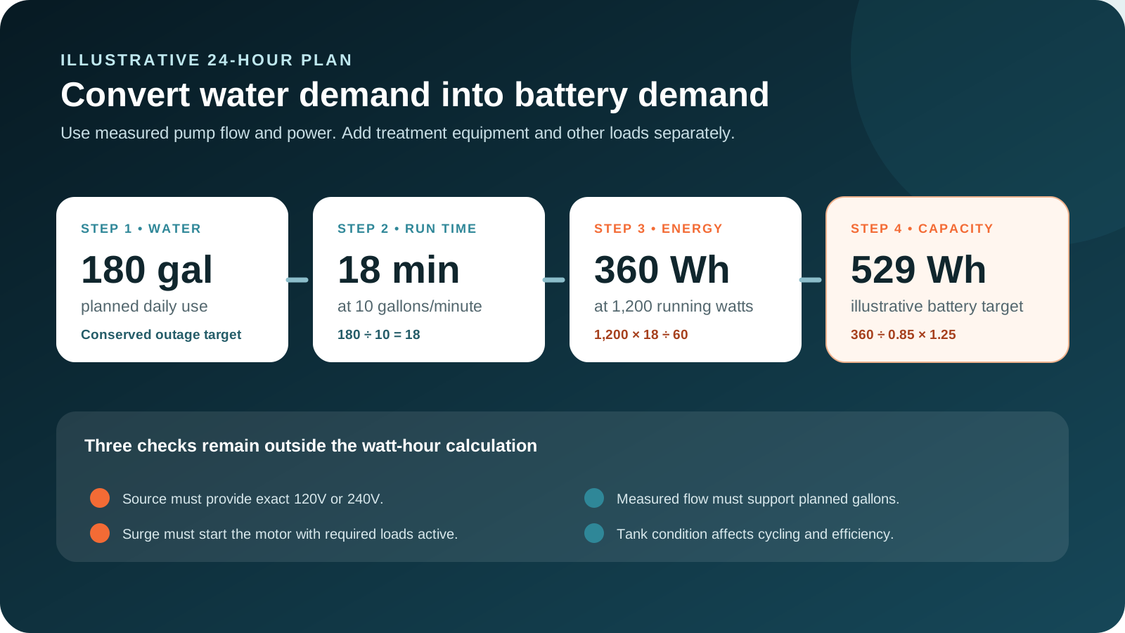
In the illustration, 180 gallons at 10 gallons per minute requires 18 pump minutes. A measured 1,200-watt running load uses 1,200 × 18 ÷ 60 = 360 watt-hours. Dividing by an illustrative 0.85 delivery factor and adding a 25 percent reserve gives 360 ÷ 0.85 × 1.25 = about 529 watt-hours. Those factors are planning assumptions, not universal battery specifications. Use the source manufacturer's usable-capacity and environmental data.
Do not confuse outage duration with pump run time. A pump may run for only a fraction of each day, while refrigeration, communications, medical devices, and heating controls consume energy for many hours. In a shared battery, reserve enough power for pump start even late in the discharge cycle. Use the Battery Runtime Calculator for the pump and the Home Backup Calculator for the combined load plan.
Follow both flows
The backup system runs from source isolation to safe water at the fixture
Map the electrical path and the water path on one page. The electrical side begins with utility and backup sources, passes through listed transfer or isolation equipment, supplies the well circuit and its controls, and ends at the motor. The water side begins at the well, passes through the pump, check valve, pressure tank, optional storage and treatment, and ends at priority fixtures.
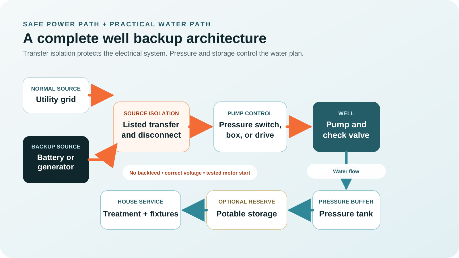
Some homes can keep the water path simple: pump, pressure tank, and fixtures. Others depend on iron treatment, softening, filtration, ultraviolet disinfection, radon treatment, acid neutralization, booster pumping, or heat trace. Decide which equipment must remain online and which can be bypassed only if the manufacturer and water professional approve a safe procedure. Never bypass treatment when doing so could expose the household to unsafe water.
Choose an architecture
Compare battery, generator, portable, and hybrid routes by the installed pump
| Backup route | Strong fit | Critical limitations to resolve |
|---|---|---|
| Installed split-phase battery | Automatic quiet response, selected-circuit or whole-home backup, frequent short outages, and solar integration. | 240V output, motor surge, usable capacity, state-of-charge reserve, pump priority, transfer architecture, and recharge. |
| Portable battery with suitable output | Smaller verified pumps, temporary resilience, or a professionally planned dedicated connection. | Many units do not provide the required 240V output. Connection, neutral, grounding, surge, weather, and automatic transfer require careful verification. |
| Portable generator | Longer outages, strong motor-start capability, scheduled pumping, and fuel-based recovery. | Correct 120/240V output, manufacturer generator sizing, transfer equipment, outdoor placement, weather protection, fuel, maintenance, and manual operation. |
| Standby generator | Automatic whole-home or selected-load service, unattended properties, larger pumps, and repeated multi-day outages. | Professional sizing, transfer, fuel supply, exercise, maintenance, load management, placement, and local requirements. |
| Hybrid battery and generator | Quiet automatic essentials, controlled pump starts, generator recharge windows, and multi-day resilience. | Compatible charging, source coordination, reserve thresholds, fuel, 240V path, controls, and a tested manual fallback. |
| Potable storage without immediate pump power | Short outages, source failure, flood contamination response, low-yield wells, and minimum drinking reserve. | Storage volume, sanitation, rotation, freeze protection, pressure delivery, treatment, and local plumbing requirements. |
Installed battery route
An installed battery can make well service nearly automatic when it provides the required split-phase output and motor-start response. Give the well circuit a protected priority. Prevent large discretionary loads from overlapping startup, and preserve a minimum state of charge for water, refrigeration, communications, heating controls, and other critical functions. For long outages, define how solar, grid recovery, or generator charging replenishes the battery.
Portable battery route
A portable unit is not automatically suitable because its marketing surge number exceeds an estimated pump value. Confirm continuous voltage configuration, short-duration motor performance, outlet and connector rating, neutral and grounding requirements, environmental limits, transfer compatibility, and the pump manufacturer's requirements. A qualified electrician should design any connection to a hardwired well circuit. Never improvise a backfeed through a receptacle.
Generator route
Use the current motor or drive manufacturer guidance. A generator must maintain adequate voltage and frequency during start, not merely display a large peak-watt number. Add other loads that remain active, then commission the pump through the final transfer path. Portable generators operate outdoors only, away from structures and openings, with exhaust directed away. Fuel handling, refueling, wet-weather use, and maintenance must follow the generator manual.
Hybrid plus stored-water route
A layered plan reduces dependence on any one component. Battery backup can carry the pressure controls, communications, refrigeration, lighting, and selected pump cycles immediately. A generator can run during planned windows to operate the pump, recharge the battery, and handle other high loads efficiently. Solar may contribute to recovery when conditions and equipment allow. Stored potable water protects the household if the pump, well, controls, source, or water quality becomes unavailable.
Permanent safety, clear operation
Use listed transfer equipment and a written switching procedure
A well pump is often hardwired. Supplying it from a backup source means more than finding a plug. The connection must isolate the utility, preserve required grounding and bonding, protect conductors, match voltage and current, maintain weather ratings, and operate the control equipment as intended. Transfer equipment may serve the whole panel, a selected-load panel, or a dedicated well circuit. The final design depends on the source, service, pump, code, and site.
| Connection point | What the professional should verify | Failure it prevents |
|---|---|---|
| Source output | 120/240V configuration, frequency, waveform where relevant, continuous rating, motor-start capability, overcurrent protection, and receptacle or terminals. | Failed start, equipment fault, overheated connection, or wrong voltage. |
| Transfer isolation | Listed switch, interlock, gateway, or approved equipment that prevents utility and backup from energizing the circuit together. | Backfeed, lineworker hazard, source conflict, and equipment damage. |
| Well circuit | Breaker, conductor, disconnect, control box, pressure switch, drive, grounding, surge protection, and labeling. | Nuisance trips, shock, damaged controls, and unsafe service work. |
| Load control | Well priority, delayed motor starts, and shedding of central air, electric heat, water heating, EV charging, or other large loads. | Overload when multiple high-demand loads overlap. |
| Operating procedure | Source startup, transfer order, load order, pressure check, shutdown, cooldown, refueling, and utility return. | Operator confusion during darkness, bad weather, or an unattended event. |
Label the pump circuit, transfer positions, generator inlet, disconnects, pressure gauge, and emergency contacts clearly. Keep instructions where they remain accessible without internet service. If the process is too complex for every intended operator, simplify the architecture or use automatic equipment with a tested fallback.
Transparent examples
Three profiles show why voltage, startup, and gallons all matter
These are calculation examples, not universal pump values or product recommendations. Each uses measured input power and delivered flow, an 85 percent illustrative delivery factor, and a 25 percent reserve. The source must still pass voltage, motor-start, connection, environment, and manufacturer compatibility checks.
120V shallow-well jet pump
- 850 W measured running
- 2,550 W measured startup
- 8 GPM delivered flow
- 240 gallons in 24 hours
- Pump run time
- 30 minutes
- Pump energy
- 425 Wh
- Planned capacity
- About 625 Wh
The energy target is modest, but the source still needs a proven 2,550-watt motor start and a safe connection to the exact 120V configuration.
240V conventional submersible
- 1,300 W measured running
- 3,900 W measured startup
- 10 GPM delivered flow
- 500 gallons in 24 hours
- Pump run time
- 50 minutes
- Pump energy
- 1,083 Wh
- Planned capacity
- About 1,593 Wh
The source must provide proper split-phase output. Load management should prevent another large motor or heating load from overlapping the pump start.
Larger 240V pump, two-day plan
- 2,200 W measured running
- 6,600 W measured startup
- 12 GPM delivered flow
- 1,080 gallons across 48 hours
- Pump run time
- 90 minutes
- Pump energy
- 3,300 Wh
- Planned capacity
- About 4,853 Wh
The larger start and energy target favor an installed battery, compatible generator, or hybrid. Stored water can reduce required pump cycles and provide a failure reserve.
Profile 1: 240 gallons ÷ 8 GPM = 30 minutes. Then 850 W × 30 ÷ 60 = 425 Wh. Finally, 425 ÷ 0.85 × 1.25 = 625 Wh. Profile 3: 1,080 gallons ÷ 12 GPM = 90 minutes. Then 2,200 W × 90 ÷ 60 = 3,300 Wh. Finally, 3,300 ÷ 0.85 × 1.25 = about 4,853 Wh.
If the same battery also runs a refrigerator, freezer, internet equipment, furnace blower, lights, medical devices, or a water-treatment system, add their energy and simultaneous output. If a generator runs them, add the background running load to the pump's starting event. Use the Generator Size Calculator to model that overlap.
Capacity cannot fix every fault
Design a response for electrical, mechanical, water, and operator failures
Battery empty or generator unavailable
Potable storage, conservation, a second recovery source, fuel readiness, and a clear relocation plan preserve options.
Motor, control, or check valve fails
Backup electricity cannot repair a failed water system. Keep contractor records, stored water, alarms, and service access ready.
Low yield or dry-well fault
Reduce flow, allow recovery, protect the pump, and never bypass low-water protection to force continued operation.
Flooding or contamination suspected
Stop using the well, switch to a safe source, and follow health-authority inspection, disinfection, and testing guidance.
Extend the exercise to common practical faults: depleted pressure tank, stuck pressure switch, tripped breaker, drive alarm, failed transfer, blocked filter, frozen pipe, leaking check valve, generator that will not start, stale fuel, battery that cannot deliver surge, solar recovery below forecast, communications outage, and no trained operator at home. Give each fault a detection method, safe boundary, responsible person, and alternative water source.
The aquifer, well, pump, controls, pressure equipment, treatment, plumbing, backup source, and water quality must all remain usable. Keep a separate potable reserve even after the electrical system passes commissioning.
Commission the real sequence
Test startup, pressure recovery, water delivery, transfer, and long-outage operation
Testing should follow the pump, controller, battery, generator, transfer, and water-treatment manuals. Coordinate electrical and well-system professionals where the test crosses both trades. Do not create an outage by pulling unsafe conductors, opening energized equipment, or bypassing protective devices.
- 1Inspect and record
Confirm labels, manuals, circuit, controls, tank, gauge, switch, treatment, wellhead, transfer, backup source, alarms, and stored-water condition.
- 2Verify normal water behavior
Observe cut-in and cut-out, run time, pressure stability, flow, noise, leakage, treatment operation, and whether the system short cycles.
- 3Transfer to backup safely
Follow the approved procedure. Confirm source voltage and operating status before applying the well circuit.
- 4Start with planned background loads
Verify the pump starts repeatedly without source overload, voltage fault, frequency problem, drive alarm, or nuisance trip.
- 5Confirm useful water service
Check pressure recovery, measured flow, treatment, storage refill, and the effect of simultaneous fixture use.
- 6Test the outage playbook
Run the conservation plan, generator window, battery reserve, alert path, shutdown, refueling, recharge, and utility-return sequence.
- 7Document results and limits
Record start behavior, watts, gallons, run time, faults, source state, safe operating steps, next maintenance, and professional corrections.
Repeat the functional test on the schedule required by the equipment and before local high-risk seasons. Exercise generators, maintain fuel safely, inspect batteries, test carbon monoxide alarms, check transfer equipment, and update written instructions. Have the well system inspected when pressure, flow, sound, cycling, taste, odor, or appearance changes. The National Ground Water Association advises professional attention when breakers trip or control indicators show a problem.
Non-negotiable boundaries
Protect people from electricity, exhaust, and unsafe water
Do not work on well wiring, controls, capacitors, transfer equipment, or pumps without the required training and safe isolation. Some control equipment can retain dangerous energy after input power is removed. Follow the exact waiting, verification, grounding, and service procedures in the manual.
Never energize household wiring through an improvised receptacle connection. Use listed transfer equipment that isolates utility and backup sources.
Operate portable generators outside, more than 20 feet from the home, with exhaust directed away from doors, windows, vents, and occupied areas.
Do not touch pumps, panels, controls, cords, or generators while standing in water or on a wet surface. Keep equipment within its weather rating.
Stay away from a flooded well and pump because of shock and contamination risk. Do not drink or wash with the water until authorities and professionals clear it.
Use bottled water or another safe source. Follow local health guidance for inspection, disinfection, flushing, sampling, and testing before resuming use.
Keep fuel, chemicals, generator refueling, and spill risk away from the wellhead. Maintain the sanitary cap, drainage, and required clearances.
After a flood, EPA guidance says to stay away from the flooded well pump, avoid using the water, obtain help to clean and disinfect the well, and pump until water runs clear after the system is returned to service. CDC guidance adds testing and the use of an alternative safe source or boiling as directed until safety is established. Chemical contamination cannot necessarily be made safe by boiling. Follow the local health department's advice for the actual event.
Installer handoff
Use this checklist before relying on well pump backup
- Well records collectedWell log, pump setting, water levels, pump model, motor model, service history, and contractor contacts are available.
- Electrical configuration verifiedVoltage, phase, wire design, breaker, conductors, disconnect, control box or drive, grounding, and surge protection are recorded.
- Startup measured or documentedThe source selection uses exact manufacturer data or qualified inrush measurement, not only horsepower.
- Water performance verifiedDelivered flow, pressure, pumping head, treatment, well yield, and pressure recovery support the outage water plan.
- Pressure tank healthyPrecharge, switch settings, drawdown, cycling, relief protection, check valve, and leaks are professionally checked where needed.
- Energy calculated transparentlyGallons, GPM, pump minutes, running watts, conversion losses, battery limits, temperature, aging, shared loads, and reserve are visible.
- Transfer is listed and labeledUtility and backup cannot energize the circuit together, and every intended operator understands the procedure.
- Large loads are managedThe well has priority, and central air, resistance heat, water heating, laundry, cooking, or EV charging cannot defeat pump start.
- Recovery is documentedGenerator fuel, charging, solar expectations, stored-water reserve, conservation, and long-outage decisions are written.
- Water safety is separateFlood, contamination, disinfection, testing, and alternative-water steps are not confused with electrical restoration.
- Complete sequence passesTransfer, motor start, pressure recovery, treatment, water delivery, source reserve, shutdown, alarms, and utility return are tested.
Common questions
Well pump backup questions
Can a portable power station run a well pump?
Some can, but only when the unit supplies the installed pump's exact 120V or 240V configuration, starts the motor through its real controls, sustains running demand, provides enough usable energy, and connects through an approved method. Many portable units provide only 120V. Verify the exact source and pump rather than relying on a generic surge claim.
How many watts does a well pump need?
There is no reliable universal number. Voltage, horsepower, motor design, control type, pumping head, pressure, efficiency, and starting behavior vary. Use the pump and motor manuals, control information, and qualified running and inrush measurements.
Does a 240V well pump always need a large whole-home system?
No. It needs a source and transfer path that provide correct split-phase voltage, adequate motor start, sufficient continuous output, and enough energy for the water plan. A selected-circuit battery or compatible generator may be appropriate without backing up every home circuit.
How long will a battery run a well pump?
Calculate gallons required, divide by measured gallons per minute, convert the pump minutes to watt-hours using measured running power, then account for losses and reserve. Runtime also depends on whether the source can start the motor at the remaining state of charge and whether other loads share the battery.
Will the pressure tank provide water during an outage?
It can provide the remaining drawdown between the current pressure and the pressure-switch cut-in point. That is normally a limited amount, not the tank's full labeled volume and not a multi-day reserve. A separate potable-water supply remains important.
Is well depth enough to size backup power?
No. The pump works against pumping water level, elevation, required pressure, and friction losses. Total drilled depth does not reveal electrical demand or delivered flow. Use the well record, pump curve, installed controls, and measured system performance.
Can I place a generator near the wellhead?
Keep generators outdoors and away from structures and openings according to current safety guidance and the manufacturer. Also protect the well from fuel, oil, exhaust, and spills. Do not refuel or store chemicals where they could contaminate the well or groundwater.
Can I drink well water after flooding if the pump works?
Do not assume so. A flooded well may be contaminated even when the electrical and pressure systems operate. Use another safe water source and follow local health, EPA, and CDC guidance for inspection, disinfection, flushing, sampling, and testing.
Match the pump exactly, conserve water deliberately, and keep a safe reserve
Record the installed motor and controls, verify 120V or 240V compatibility, prove motor start with real background loads, and calculate energy from planned gallons and measured flow. Then protect the connection with listed transfer equipment, keep stored potable water available, test the full sequence, and maintain a long-outage recovery path that does not depend on one battery, generator, or pump.
Technical and safety sources
- Franklin Electric: 2026 AIM manual and submersible motor application resources
- Franklin Electric: residential submersible pump voltage, horsepower, and flow examples
- National Ground Water Association: Well Owners Guide
- Ready.gov: emergency water storage guidance
- U.S. EPA: what to do with a private well after a flood
- CDC: well disinfection and testing after an emergency
- CDC: portable generator carbon monoxide safety
- Electrical Safety Foundation International: transfer switches and backfeed prevention
Reviewed July 26, 2026. Pump and motor documentation, controls, battery or generator instructions, site conditions, water quality, and local electrical, plumbing, well, fuel, and health requirements control the final design. Use qualified well-system and electrical professionals where required.