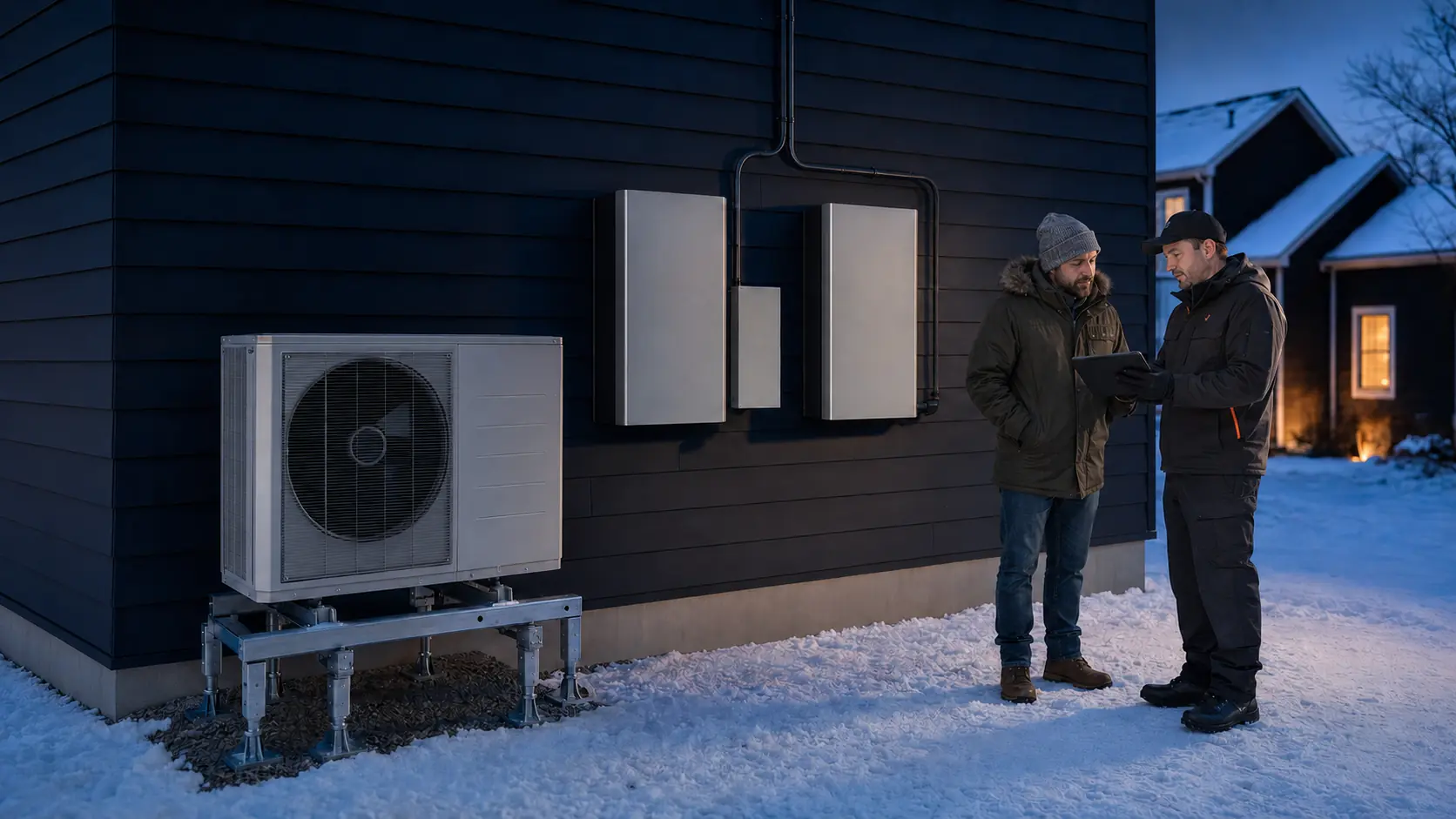
Heat pump backup power
A heat pump is not one simple appliance load. The outdoor compressor, indoor air handler or room units, thermostat, communicating controls, crankcase and base-pan heaters, condensate equipment, pumps, defrost sequence, and possible auxiliary resistance heat can use different circuits and behave differently as outdoor temperature changes. Reliable backup begins with the exact matched system and its native control logic. Measure the complete installation, choose which modes the backup source will support, and test the coldest credible operating condition rather than relying on tonnage, breaker size, or a generic wattage chart.

A heat pump can run on backup power, but the system must pass power, energy, control, and temperature tests.
A properly designed 120/240V battery, generator, or hybrid system can support many residential heat pumps. Success depends on the actual equipment. A fixed-speed compressor may impose a demanding start. An inverter-driven compressor may ramp more gently but still reach substantial input at high capacity and may have source-quality requirements. The indoor unit, thermostat, pumps, zone controls, defrost cycle, and any auxiliary heat must remain coordinated.
Electric resistance strips are often the design boundary. A backup source that can operate the compressor and blower may be far too small for a multi-kilowatt heat kit. The safe solution is not to defeat controls. It is to document the equipment, determine which operating modes the manufacturer supports, and have the HVAC and electrical design intentionally support, stage, shed, lock out, or replace auxiliary heat with an approved alternative. Cold-weather capacity, house heat loss, outage duration, and recharge then determine whether the result is useful.
Installed battery system
Strong when it provides the exact 120/240V architecture, holds compressor demand, manages heat strips, and carries the planned cold interval.
Plan the battery routeGenerator backup
Can support sustained heating or recharge a battery when voltage, waveform, transfer, fuel, placement, and cold starting are resolved.
Plan the generator routeHybrid recovery
Uses stored energy for instant, quiet operation and a generator or solar path to restore reserve before the next difficult interval.
Build the hybrid planDual-fuel strategy
Uses an approved fuel-burning heat source when electric heat-pump demand would exceed the available backup system.
Plan the dual-fuel routeClassification comes before capacity
Identify what moves heat, what distributes it, and what supplies backup heat
Start with the installed equipment, not the thermostat label. A central air-source heat pump normally has an outdoor compressor unit and a ducted indoor air handler or furnace coil. A ductless mini-split has one outdoor unit and one or more indoor heads. A multi-split can serve several zones whose simultaneous calls influence outdoor-unit demand. A ground-source system uses a compressor, indoor distribution equipment, and one or more loop or well pumps. A packaged unit combines major assemblies in one cabinet. Each architecture has a different circuit map.
The compressor can be fixed speed, staged, or variable speed. A conventional fixed-speed compressor starts at full demand and cycles off when the thermostat is satisfied. A two-stage system has more than one capacity. An inverter-driven system varies compressor speed and may run for long periods at low or moderate input, then increase demand as outdoor conditions or indoor recovery require. Do not assume an inverter means a small backup load. It changes the shape of demand, not the need to verify maximum input and source compatibility.
Outdoor unit plus air handler
Map the compressor, indoor blower, thermostat, controls, condensate equipment, heat kit, and any zoning accessories.
Mini-split or multi-split
Confirm the outdoor supply, number of indoor heads, communication wiring, condensate pumps, operating zones, and low-temperature limits.
Compressor plus water loop
Include loop pumps, well pumps where applicable, circulation, controls, blower or hydronic distribution, and auxiliary heat.
Heat pump plus furnace
Document the approved changeover logic, thermostat, outdoor sensor, furnace circuit, heat-pump circuit, and transfer behavior.
Next identify supplemental and emergency heat. A central heat pump may have electric resistance elements inside the air handler. A dual-fuel system may switch to a gas, propane, or oil furnace. Some homes retain a boiler, wood appliance, or separately controlled room heater as an independent fallback. The backup plan must distinguish an automatic system component from a separate emergency procedure. Never assume a thermostat setting safely changes electrical requirements unless the equipment documentation confirms what that setting does.
Finally, record the exact matched combination of indoor and outdoor units. Rated capacity and efficiency can depend on the pairing, refrigerant charge, airflow, controls, and installed configuration. ENERGY STAR’s current specification treats split-system certification as a matched combination and stresses proper charge and airflow. A model number from only the outdoor cabinet is not a complete system record.
One thermostat can hide several circuits
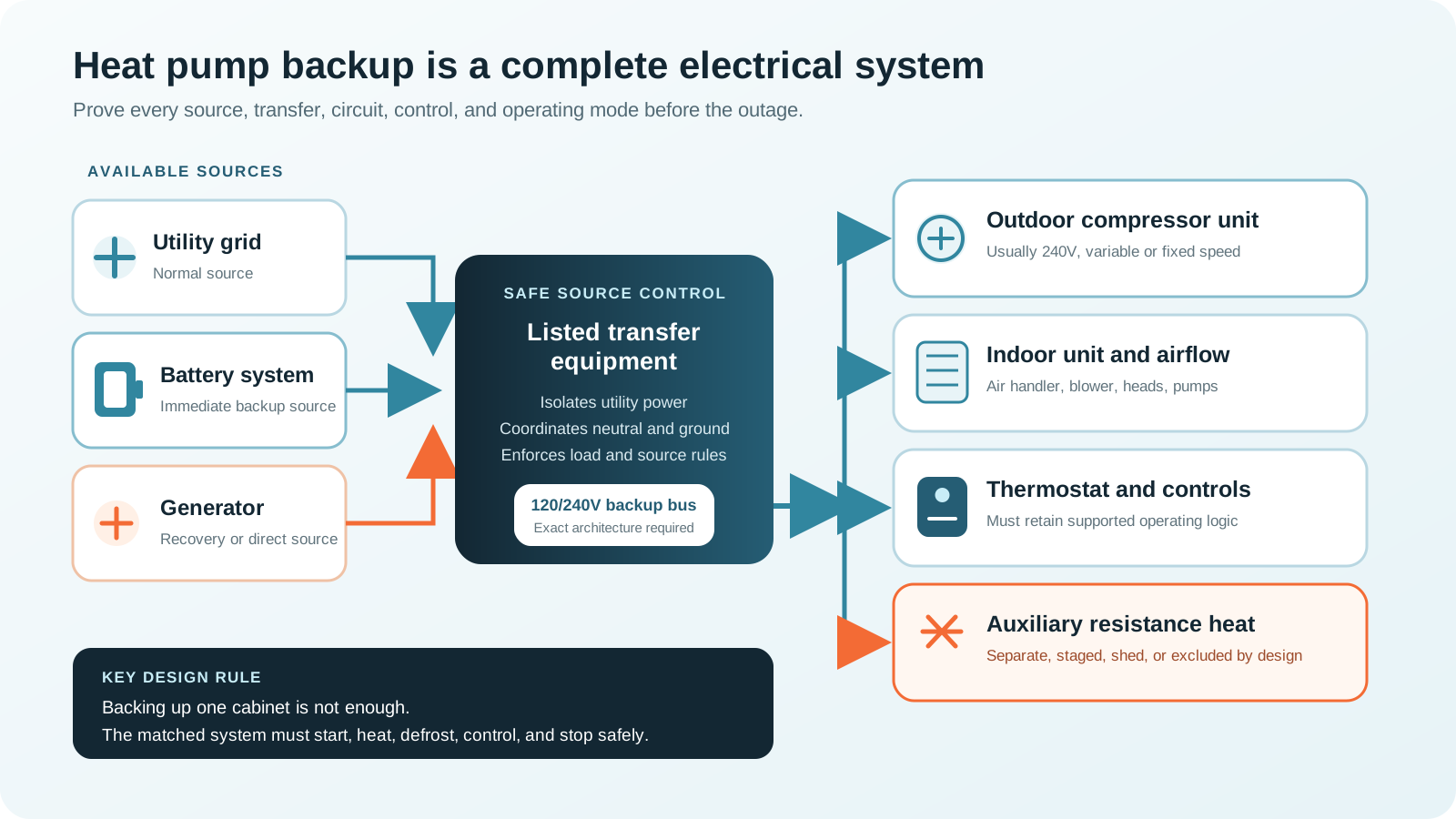
Map outdoor, indoor, control, and auxiliary power separately
Many central heat pumps use a 240V outdoor branch circuit and a separate indoor-unit circuit. The indoor air handler may be 120V or 240V. A heat kit can use one or more large 240V breakers in addition to the blower and controls. A dual-fuel furnace may use a separate 120V circuit. Ductless equipment commonly uses a 208/230V supply at the outdoor unit, but the exact arrangement varies. Some indoor heads receive power through the outdoor unit; others use separate feeds. Ground-source equipment can add circulation pumps on their own circuits.
Backup equipment must reproduce the voltage and conductor configuration that each supported load requires. A source with a 120V receptacle cannot operate a 240V compressor. A 240V output is not automatically compatible with a home’s split-phase 120/240V loads, neutral requirements, transfer equipment, or grounding arrangement. The electrician must verify the actual service, backed-up panel, line-to-line and line-to-neutral loads, overcurrent protection, disconnects, and neutral behavior.
Outdoor circuit
Voltage, phase, breaker, disconnect, minimum circuit ampacity, maximum protective device, and measured input.
Indoor circuit
Air handler, blower, indoor heads, controls, pumps, condensate equipment, and zone devices.
Control path
Thermostat, communicating link, outdoor sensor, interface modules, relays, and approved source-change logic.
Auxiliary circuit
Heat-strip stages or alternate furnace, including every breaker and the rules that permit or prevent operation.
Do not infer normal demand from the breaker. A branch-circuit rating protects wiring and accommodates permitted operating conditions. Minimum circuit ampacity and maximum fuse or breaker information help the installer design the circuit; they are not the same as measured watts. Likewise, heat-pump tonnage describes thermal capacity, not electrical input. A three-ton system does not consume three kilowatts by definition, and two systems with the same nominal capacity may have very different electrical behavior.
Create a one-line diagram that shows the normal utility source, backup source, transfer equipment, backed-up bus, outdoor unit, indoor unit, control power, auxiliary heat, and every intentional load-management device. Label what remains unpowered. If the design uses a critical-load panel, confirm that all required heat-pump components are on that panel. If one communicating module or indoor blower is left on the normal panel, the outdoor unit may have power but still cannot deliver heat.
Voltage at the outdoor disconnect is not proof. A successful test confirms thermostat demand, indoor airflow, compressor operation, capacity change, normal defrost where safely testable, auxiliary or dual-fuel behavior as designed, stable shutdown, and a clean restart after transfer.
Build one exact equipment record
Collect labels, manuals, performance tables, control settings, and measured evidence
Photograph the model and serial labels of the outdoor unit, indoor unit, heat kit, furnace if present, thermostat or controller, interface modules, pumps, and transfer equipment. Save the installation, operation, service, and application manuals. Record breaker positions and disconnects without opening energized equipment. Ask the HVAC contractor for the matched-system performance data at relevant outdoor temperatures, not just the nominal rating at a mild test point.
Record the complete heat-pump system
Keep this file with the transfer procedure, emergency contacts, and commissioning results.
- System typeCentral, ductless, packaged, ground source, dual fuel
- Electrical supplyVoltage, phase, circuits, breakers, disconnects
- Matched equipmentOutdoor, indoor, heat kit, furnace, pumps
- ControlsThermostat, zones, sensors, interfaces, lockouts
- PerformanceCapacity and input by outdoor temperature
- Measured behaviorPeak, steady input, modes, cold-hour Wh
Ask for a mode table
Record standby, fan-only, low and high compressor operation, fixed-speed start, cooling, heating, defrost, crankcase or base-pan heater use, auxiliary stages, emergency heat, and dual-fuel changeover. For each supported mode, note which circuits energize, the highest observed demand, typical stabilized input, expected duration, and any source-quality requirement. Mark modes that the backup design intentionally excludes.
| Record | Why it matters | Where it may be found | Who should verify |
|---|---|---|---|
| Exact voltage and circuit map | The source and transfer path must reproduce every required supply and conductor arrangement. | Nameplates, manuals, breakers, disconnects, wiring documentation. | HVAC technician and electrician. |
| Fixed-speed start or inverter maximum | Determines the short event or sustained high input the source must hold. | Manufacturer data and qualified measurement through complete operation. | HVAC technician and electrician. |
| Heating capacity by temperature | Shows whether the compressor can meet building heat loss without supplemental heat. | Matched-system application and performance tables. | HVAC designer or trained contractor. |
| Heat-strip stages | Resistance heat can dominate both output and battery-capacity requirements. | Heat-kit label, air-handler data, breaker map, thermostat configuration. | HVAC technician and electrician. |
| Defrost and support heat | Defrost changes operating state and may call auxiliary heat to temper indoor air. | Sequence of operation, service manual, controlled commissioning test. | Qualified HVAC technician. |
| Cold-hour energy | Converts changing compressor input and duty into a usable storage target. | Whole-system monitoring at representative outdoor conditions. | Homeowner with professional review. |
| Control and source requirements | Power quality, phase relationships, grounding, neutral, and communications can affect operation. | Equipment, controller, battery, inverter, generator, and transfer documentation. | HVAC technician and electrician. |
Locked-rotor amps, rated-load amps, minimum circuit ampacity, maximum overcurrent protection, and rated input describe different things. A locked-rotor value can inform fixed-speed starting analysis but is not a substitute for a supported source-sizing method. An inverter system may not publish a conventional locked-rotor value because its electronics control motor acceleration. Minimum circuit ampacity is for circuit design. Maximum overcurrent protection is not the unit’s normal draw. Use each value for its intended purpose.
Resolve equipment problems before backup commissioning. Restricted airflow, dirty filters or coils, low refrigerant charge, failed sensors, repeated fault codes, unusual ice, drain problems, short cycling, failed crankcase heat, or unreliable auxiliary stages can make a backup test misleading and can damage equipment. Backup power does not repair a marginal heat pump. It may expose the weakness under the most difficult conditions.
Demand has shape as well as size
Fixed-speed compressors, staged units, and inverters challenge backup sources differently
A fixed-speed compressor can draw a brief high starting current before settling to its running condition. The backup inverter or generator must maintain acceptable voltage and frequency through that event while the indoor blower, pumps, refrigeration, lights, and other selected loads are active. If voltage collapses, the compressor may fail to start, protective controls may trip, relays may chatter, or the system may enter a fault. Repeated failed starts are not a valid test method.
An inverter-driven heat pump often starts more gradually because power electronics control compressor speed. That can reduce the abrupt motor-start challenge, but it does not guarantee compatibility. The source must still support the maximum electrical input the native controls can request, the indoor-unit demand, defrost transitions, standby heaters, and other loads. The inverter electronics may also have limits for voltage, frequency, waveform, phase balance, grounding, or generator operation. Confirm the exact manufacturer guidance rather than treating “soft start” as a universal feature.
Two-stage and variable-capacity systems can change demand during a long heat call. A mild-weather measurement at low speed may understate backup output for a cold start after the house has cooled. Conversely, sizing only from a circuit maximum can grossly overstate normal battery energy. Record the highest credible instantaneous or short-duration demand and the energy profile separately.
- StandbyControls ready
Thermostat, communications, sensors, and heaters may consume power.
- DemandIndoor unit starts
Blower, pump, head, dampers, or zone controls establish distribution.
- CompressorFixed or ramped start
The outdoor unit starts and verifies operating conditions.
- CapacityInput changes
Staging or inverter speed responds to load and outdoor temperature.
- TransitionDefrost or stop
The system changes mode, recovers, and returns to stable heating.
A field-installed compressor soft starter can help some compatible fixed-speed systems, but it is not a generic accessory. The heat-pump manufacturer, soft-start manufacturer, HVAC contractor, electrician, and backup-source documentation must support the application. Do not install a soft starter on an inverter-driven compressor unless the equipment manufacturer explicitly allows it. Do not use an accessory to conceal a failing compressor, weak capacitor, low voltage, or undersized circuit.
Test overlap intentionally. The highest whole-home event may occur when the heat pump increases capacity as a well pump, sump pump, refrigerator, or freezer starts. A managed system can defer lower-priority motors, water heating, vehicle charging, cooking, laundry, or auxiliary strips. Output planning should use the largest allowed overlap after load-management rules, not an impossible condition where every appliance starts together and not an optimistic condition where the heat pump is alone.
The cold-weather control boundary
Defrost and auxiliary heat must be designed, not discovered during an outage
During air-source heating, the outdoor coil can accumulate frost. The system periodically enters a defrost sequence to restore heat transfer. Depending on the design, the reversing valve changes refrigerant flow, the outdoor fan may stop, the compressor continues or changes operation, and the indoor system may use auxiliary heat to avoid delivering cold air. ASHRAE notes that frost restricts heat transfer and airflow and that defrost cycles are used to clear the outdoor coil. The exact sequence belongs to the installed equipment.
Defrost matters to backup in two ways. First, it can change instantaneous demand and the combination of active components. Second, it can temporarily reduce delivered indoor heat and increase energy use. A system that runs normally for an hour on backup can still fail when it enters defrost. Commissioning should include the manufacturer’s supported test procedure when conditions and equipment allow. Do not force a reversing valve, sensor, contactor, or service control outside the prescribed process.
Auxiliary electric resistance heat is more direct: electrical input becomes heat. A heat kit can contain several stages and may require multiple breakers. The thermostat may call strips during defrost, a large indoor temperature recovery, a low outdoor temperature, compressor fault, or emergency-heat mode. Even one stage can be much larger than the compressor’s typical input. Therefore, “my heat pump uses 2,000 watts” is not a usable backup statement if a 5, 10, or 15 kW heat kit can energize without an intentional plan.
Back up every stage
Requires output, storage, wiring, transfer, and generator capacity for the largest permitted heat-strip overlap.
Allow limited strips
Uses approved controls or load management so only a defined stage can operate on backup.
Block resistance heat
Permitted only through a supported design that preserves defrost, equipment protection, and control logic.
Use alternate heat
A dual-fuel furnace or independent safe heat source carries conditions the electrical backup cannot support.
Do not simply switch off a heat-strip breaker and assume the heat pump remains protected and comfortable. Some systems use supplemental heat during defrost, for low-temperature capacity, or for fault recovery. An approved backup configuration may use thermostat settings, an equipment interface, a load-management relay, a transfer-system output, or a defined operating mode. The method must be supported by the system and commissioned by qualified professionals.
Emergency heat is not a low-energy setting. On many systems it disables compressor heating and uses resistance heat or the alternate furnace. The actual behavior varies. Label the approved outage mode at the thermostat and in the operating card. Everyone in the home should know which setting is normal, which is for backup power, and which indicates a heating-system fault.
If the available source cannot support the system’s required native modes, reduce the backup scope, add managed output and storage, use an approved alternate heat source, or choose a different recovery architecture.
Electrical power does not guarantee enough heat
Compare low-temperature heating capacity with the home’s heat loss
A backup source can keep the heat pump energized while the house still cools. Air-source heating capacity and efficiency change with outdoor temperature, while building heat loss usually rises as the indoor-outdoor temperature difference grows. The outdoor temperature where the heat pump’s available capacity no longer equals the building load is a balance point. Controls may add supplemental heat or switch sources before, at, or after that point depending on the design.
Use a room-by-room or whole-building load calculation for the intended design condition and matched-equipment performance data at several outdoor temperatures. ENERGY STAR’s current cold-climate criteria require verified low-ambient performance, including capacity at 5°F relative to 47°F and controls verification. Those criteria help identify equipment, but they do not prove that a particular unit is sized for a particular house, duct system, altitude, installation, thermostat setup, or backup source.
Building improvements can materially reduce backup demand. Air sealing, insulation, repaired duct leakage, clean filters, correct airflow, and reasonable zoning reduce the thermal load the heat pump must meet. DOE’s cold-climate selection guidance emphasizes accurate load calculations and addressing enclosure and duct problems. A tighter home can remain safe longer if the heat pump is unavailable and can require fewer battery kilowatt-hours when it is running.
| Temperature question | Evidence to collect | Backup implication |
|---|---|---|
| What is the local design condition? | Climate design data and the household’s credible outage scenario. | Defines the cold or hot boundary the plan is expected to cover. |
| What is building heat loss? | Current Manual J or equivalent load calculation with real envelope and ducts. | Shows the delivered heating capacity required to hold the target indoor condition. |
| What can the matched heat pump deliver? | Manufacturer capacity and input tables at relevant outdoor and indoor conditions. | Shows compressor capacity, electrical input, and possible supplemental need. |
| When does alternate heat engage? | Thermostat, sensor, equipment, and dual-fuel control configuration. | Determines whether a high electrical load or fuel-burning source enters the plan. |
| How quickly will the house cool? | Envelope performance, wind exposure, thermal mass, starting temperature, occupied rooms. | Informs reserve, setback limits, zoned refuge, and fallback timing. |
Avoid deep thermostat setback before a forecast outage unless the equipment professional recommends it. A large recovery request can command maximum compressor speed and auxiliary heat. Heat pumps often perform best with steady setpoints. During an outage, a modest target temperature, closed doors to unused areas where the distribution design permits, reduced ventilation that remains safe, and protection of vulnerable plumbing may conserve energy without triggering an aggressive recovery.
For ductless systems, select the rooms that truly need conditioning. One indoor head may create a warm refuge with far less whole-home demand, provided plumbing, occupants, and the building can tolerate cooler unserved rooms. Multi-zone systems do not always reduce outdoor-unit input in direct proportion to the number of heads turned off. Confirm minimum and maximum modulation, refrigerant configuration, freeze risks, condensate needs, and manufacturer operating guidance.
Replace assumptions with an operating profile
Measure highest demand and cold-hour energy as separate targets
The output target answers, “Can the source keep the system operating right now?” The energy target answers, “How long can it keep operating?” A battery can contain ample kilowatt-hours but have insufficient 240V output or compressor-start capability. A powerful generator can start the system but run out of fuel or fail in severe weather. Measure both.
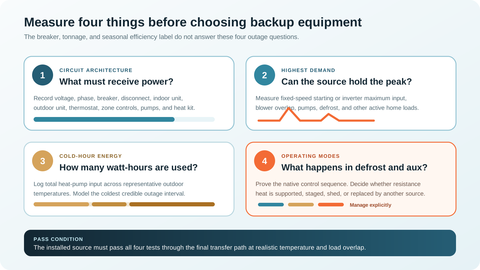
Use qualified instrumentation appropriate to the hardwired circuits. A central heat pump should not be routed through a household plug meter. Ask the electrician or HVAC technician to record outdoor-unit power, indoor-unit power, any heat-strip circuits, control power, and whole-home overlap. For fixed-speed equipment, capture a supported start profile. For variable equipment, capture low, typical, and maximum input plus transitions. Log voltage and frequency at the load if source behavior is part of the test.
For energy, monitor at representative outdoor temperatures long enough to include cycling, modulation, standby heaters, and defrost. A mild afternoon average cannot represent the coldest night. If direct cold-weather data is not yet available, use manufacturer input tables and a conservative thermal model, then update the design after a season of monitored operation. Document uncertainty as margin rather than inventing precision.
Include source overhead and standby consumption where relevant. An installed inverter, transfer controller, battery heater, communications gateway, generator battery charger, and monitoring system can consume energy even when the compressor is off. Cold installation temperature can affect battery charge or discharge capability. Use the battery manufacturer’s temperature and usable-capacity limits, not a universal percentage.
Measurement should preserve equipment warranties and safety. Do not remove covers, clamp conductors, force service modes, alter thermostat wiring, or change breakers unless qualified and authorized. The objective is a defensible system profile, not a risky homeowner experiment.
Storage is a weather-dependent result
Calculate the planned interval, then design the next recovery window
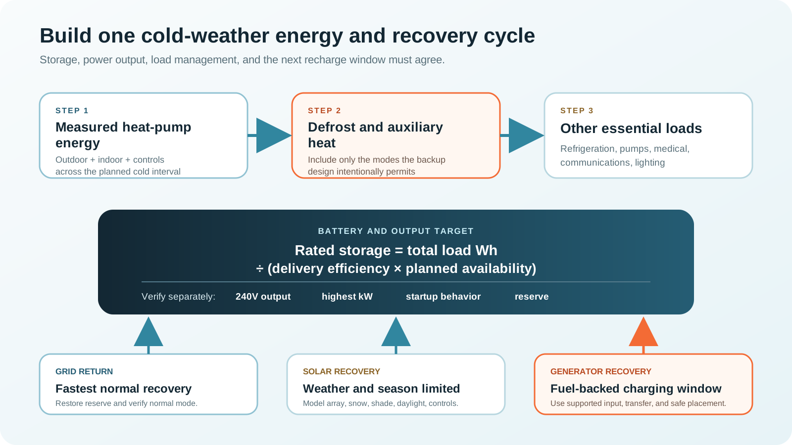
Heat-pump energy is best calculated from an interval profile. Divide the outage into conditions that meaningfully change demand, such as early evening, cold overnight, morning recovery, and daytime solar hours. For each interval, use measured or supported average input for the intended thermostat setting and operating mode. Add other essential loads. Then divide delivered energy by the backup system’s planned delivery factor and retained reserve.
Example interval calculation
A monitored inverter heat pump averages 1,150 W across a 12-hour cold-night interval, including its indoor unit and normal defrost behavior but with resistance heat intentionally excluded by an approved control design. Heat-pump energy is 1,150 × 12 = 13,800 Wh. Selected refrigeration, communications, lighting, and a pump add 2,200 Wh. Total delivered load energy is 16,000 Wh.
Translate to rated storage
If the planning model uses 90 percent AC delivery efficiency and retains 10 percent of rated battery capacity as unavailable reserve, the combined factor is 0.90 × 0.90 = 0.81. Required rated capacity is 16,000 ÷ 0.81 = about 19,753 Wh. Temperature, aging, standby demand, uncertain weather, and recharge timing can justify more margin.
This example is not a standard heat-pump wattage. Replace every input. A colder night, leakier house, higher setpoint, fixed-speed system, large duct loss, several indoor heads, ground-loop pumps, or permitted heat strips can change the result substantially. A well-insulated small zone with a variable mini-split may use less. Storage must follow the measured home, equipment, and weather objective.
Solar recovery is useful but seasonal. Winter production can be constrained by short daylight, low sun angle, cloud, snow, shading, roof orientation, array size, controller limits, and battery state. Compare credible daily solar energy with the heat pump’s daily electrical energy, not panel nameplate watts with compressor watts. A large array can still have a poor snow-covered day.
Generator recovery can reduce required battery capacity if the battery system explicitly accepts generator charging and the generator can provide stable charging power while any direct loads operate. Set a charging window, reserve threshold, fuel plan, and stopping condition. A generator that only runs a lightly loaded inverter inefficiently for many hours may be less practical than scheduled higher-rate charging, but every operating limit must follow the equipment documentation.
The grid-return plan matters too. After an extended outage, the battery may recharge while the heat pump, water heating, refrigeration, and other loads return. Coordinate maximum grid charging and home demand to avoid overloading service equipment or creating an expensive uncontrolled peak where utility rate structures apply. The transfer system should return the heat pump to its normal approved mode and clear any temporary load-management state.
Choose an architecture around the equipment
Compare battery, generator, hybrid, dual-fuel, and zoned-refuge routes
| Route | Best fit | Main strengths | Critical checks | Primary boundary |
|---|---|---|---|---|
| Installed home battery | Automatic central or zoned heat-pump coverage with defined runtime. | Fast transfer, quiet operation, managed 120/240V loads, no engine exhaust during discharge. | Continuous and short-duration output, fixed or inverter behavior, heat strips, energy, temperature, transfer, recharge. | Finite stored energy and possible high cold-weather demand. |
| Portable battery system | Compatible smaller ductless or specially designed limited system. | Portable, quiet, no combustion during discharge. | 240V output where required, hardwired connection, equipment support, capacity, grounding, neutral, weather protection. | Most central systems need more output, energy, and permanent connection than a simple portable unit provides. |
| Portable generator | Extended outage with trained operation and safe outdoor placement. | Fuel-backed duration and direct support or battery charging. | Starting and maximum input, waveform, voltage regulation, 120/240V transfer, fuel, cold start, CO, weather. | Noise, fuel, maintenance, placement, operator availability, and source-quality compatibility. |
| Standby generator | Automatic sustained heating and broader essential loads. | Automatic transfer and strong continuous output when fuel is reliable. | Load calculation, fuel supply, transfer, cold-weather rating, heat-strip policy, maintenance, location. | Fuel interruption or mechanical failure still needs a fallback. |
| Hybrid battery and generator | Immediate quiet operation with planned multi-day recovery. | Battery handles transfer and variable load; generator runs in scheduled charging or high-load windows. | Supported charging path, source isolation, reserve, controls, direct-load rules, fuel, manual fallback. | More components and control states require disciplined commissioning. |
| Dual fuel or refuge zone | Homes where full electric heat is too demanding for the backup objective. | Can reduce electrical load by using a furnace or conditioning only a protected zone. | Approved changeover, combustion safety, fuel, freeze protection, thermostat logic, room-to-room needs. | Does not automatically protect every room, pipe, or occupant. |
Installed battery route
An installed battery can support the heat pump through a managed whole-home system or backed-up panel. Confirm true 120/240V capability where required, continuous output at the installation temperature, fixed-speed starting or inverter maximum input, indoor-unit circuits, controls, and permitted auxiliary modes. The system should enforce load priorities automatically so a water heater, range, vehicle, dryer, or heat strips cannot consume reserve unexpectedly.
Battery location must follow the listing, manufacturer instructions, fire and building requirements, and local authority. Cold garages and exterior installations may have reduced charge capability or require internal conditioning. Do not assume a battery can accept full solar or generator charge while simultaneously serving the heat pump. Model combined input and output limits.
Generator route
A generator must do more than meet a watt total. It must provide the exact voltage and phase arrangement, maintain voltage and frequency during compressor and blower changes, coordinate neutral and grounding through approved transfer equipment, and operate within the heat-pump manufacturer’s source requirements. Inverter generators may offer tighter output regulation, but compatibility belongs to the exact equipment documentation and installed test.
Portable generators belong outdoors at least 20 feet from the home according to current CPSC guidance, with exhaust directed away from the home and all building openings. Never use one in a home, basement, garage, shed, porch, or carport. Use listed transfer equipment installed by a qualified electrician. Plan cold starting, fuel storage and rotation, refueling shutdown, weather protection that preserves ventilation, maintenance, and CO alarms.
Hybrid route
A hybrid system can let the battery handle immediate transfer, nighttime heat, thermostat controls, and short compressor changes while a generator restores reserve during a planned daytime window. It may also let the generator run at a more useful load instead of starting for every thermostat call. Solar can contribute when weather permits. The architecture must specify whether the generator powers the heat pump directly, charges the battery, or does both, and how sources remain isolated.
Set state-of-charge thresholds around the next cold interval, occupants, fuel, and fallback. A simple example is to retain a protected reserve for one heat cycle, communications, and freeze-critical pumps, then start recovery well before the battery reaches that boundary. Document manual steps if automatic controls fail.
Dual-fuel and refuge-zone route
A dual-fuel system can use the heat pump in moderate weather and a fuel-burning furnace when temperature, source capacity, battery reserve, or control strategy calls for changeover. The furnace still needs electrical backup for controls, ignition, inducer, blower, thermostat, and accessories. Use the approved thermostat and interface logic. Do not energize a furnace and heat-pump coil in an unsupported combination.
A refuge-zone plan can power one ductless heat pump or a smaller heating zone while the central system remains off. It can materially reduce backup demand, but it must account for bedrooms, infants, older adults, medical needs, bathrooms, remote plumbing, fire-sprinkler piping, and interior doors. Use temperature sensors in vulnerable areas and a predefined escalation point for relocation or alternate heat.
Connect runtime to a real recovery source
Battery reserve, generator fuel, solar seasonality, heat-pump demand, and the next cold night belong in one operating plan.
Permanent HVAC needs a designed power path
Use listed transfer equipment and intentional load management
Central and most ductless heat pumps are permanently connected equipment. Appropriate backup can use a whole-home battery gateway, automatic transfer switch, manual transfer switch, critical-load panel, generator interlock arrangement where permitted, or another listed system accepted for the exact application. The design depends on service equipment, source, load, local code, listings, overcurrent protection, disconnects, neutral arrangement, grounding, and the authority having jurisdiction.
Never connect a generator to a building receptacle with a double-male cord. Never energize the home while the utility remains connected. OSHA warns that a generator connected without proper transfer isolation can backfeed utility wiring and endanger utility workers and others. Do not improvise a 240V connection from unmatched outlets, modify an HVAC disconnect as a temporary inlet, or route cords through snow, standing water, doors, or windows.
Automatic source and load control
Useful when the heat pump is a central priority and lower-value loads can be shed based on output and reserve.
Defined circuits only
Can isolate HVAC and essential loads, but every outdoor, indoor, control, pump, and supported auxiliary circuit must be included.
Manual or automatic isolation
Coordinates utility isolation, source conductors, neutral and grounding, overcurrent protection, and a repeatable operating sequence.
Load management can be static or dynamic. Static design leaves large loads off the backed-up bus. Dynamic design uses relays, energy management, or source controls to shed loads when heat-pump demand or battery state requires it. Heat strips deserve their own rule. Other common shed loads include water heating, EV charging, electric range, clothes dryer, spa, pool equipment, and nonessential cooling or heating zones.
Control changes must fail safely. If a network gateway, wireless thermostat, current sensor, relay, or cloud service fails, the home should enter a known supported state. Critical functions should not depend solely on internet access. Label manual overrides, but prevent an override from exceeding the source or energizing an unsafe equipment combination.
Coordinate service after an outage. When utility power returns, the battery may recharge, the heat pump may recover indoor temperature, and delayed loads may restart. A staged return can protect service capacity and preserve comfort. Confirm which settings reset after a power loss and whether thermostat clocks, outdoor sensors, communicating equipment, generator exercisers, or load-control modules require attention.
Three transparent planning examples
Apply the method to the measured home, not the example label
These profiles demonstrate arithmetic and architecture choices. They are not appliance wattage recommendations. Each assumes qualified measurement, approved controls, and 90 percent AC delivery efficiency with 90 percent planned battery availability, giving a combined delivery factor of 0.81. Replace every number and reserve assumption with the installed system’s data.
Single-zone cold-climate mini-split
- Dedicated 240V outdoor-unit supply with one indoor head.
- Highest measured system input: 2,150 W.
- Cold-night average system input: 920 W for 12 hours.
- Other selected loads: 1,800 Wh across the interval.
- No electric resistance heat in the approved system design.
- Heat-pump energy
- 11,040 Wh
- Total delivered load
- 12,840 Wh
- Rated storage target
- 15,852 Wh
- Output test
- 2,150 W + overlap
Calculation: 920 × 12 = 11,040 Wh. Add 1,800 Wh, then divide 12,840 by 0.81. The design still needs compatible 240V output, transfer, temperature margin, and recovery.
Central variable-capacity heat pump
- 240V outdoor unit, 240V air handler, communicating controls.
- Highest permitted compressor and indoor overlap: 5,400 W.
- Modeled cold interval: 3,100 W average for 10 hours.
- Other essential loads: 3,200 Wh.
- Large resistance heat kit shed by an approved backup mode.
- Heat-pump energy
- 31,000 Wh
- Total delivered load
- 34,200 Wh
- Rated storage target
- 42,222 Wh
- Output test
- 5,400 W + overlap
Calculation: 3,100 × 10 = 31,000 Wh. Add 3,200 Wh, then divide 34,200 by 0.81. This profile shows why full central electric heat can need substantial storage even when starting is manageable.
Dual-fuel cold-outage strategy
- Heat pump used in moderate weather; gas furnace approved below changeover.
- Furnace and required controls use 480 W during a heat call.
- Severe-day duty cycle: 60 percent across 24 hours.
- Other essential loads: 2,500 Wh.
- Heat-pump outdoor unit remains off in the defined cold-outage mode.
- Furnace energy
- 6,912 Wh
- Total delivered load
- 9,412 Wh
- Rated storage target
- 11,620 Wh
- Output test
- Furnace start + overlap
Calculation: 480 × 24 × 0.60 = 6,912 Wh. Add 2,500 Wh, then divide 9,412 by 0.81. The system still needs fuel, combustion safety, furnace transfer, and verified changeover controls.
Do not compare storage figures without the service objective. Profile 1 protects one conditioned zone for 12 hours. Profile 2 carries a central system for 10 hours. Profile 3 uses another fuel for 24-hour severe-cold heating. The “smallest” solution is not automatically best if it leaves vulnerable rooms or plumbing unprotected. The “largest” solution is not automatically resilient if it has no recharge source.
Combine heat-pump demand with every allowed overlap
Use measured watts, interval energy, reserve, output, voltage, and recharge. Then confirm the result under the final transfer architecture.
The same equipment has two outage seasons
Commission winter heating and summer cooling as different operating cases
Winter backup focuses on low-temperature capacity, frost, defrost, auxiliary heat, freeze protection, and short solar days. Summer backup removes the defrost and heating-strip problem but can create long cooling duty, high outdoor-unit input, indoor humidity concerns, and heavy overlap with refrigeration, well pumps, and dehumidification. A source proven during a mild heating day is not automatically proven during peak cooling, and the reverse is also true.
For cooling, define the health and property objective. It may be whole-home comfort, one cool refuge for vulnerable occupants, humidity control, medication protection, or enough cooling to sleep. A ductless zone can reduce demand when it safely meets the objective. Central load management can prioritize the heat pump while shedding water heating, cooking, laundry, and EV charging. Do not block required condensate pumps or drainage.
For heating, choose a minimum safe indoor target and monitor remote areas. Pipes can freeze in cabinets, crawlspaces, exterior walls, garages, and rooms beyond the protected zone even when the occupied room feels comfortable. Keep temperature sensors where damage would begin, not only beside the thermostat. Identify how long the home can coast if the heat pump faults and where occupants will move if reserve falls.
Preserve heat and plumbing
Use steady settings, manage strips, close avoidable losses, monitor vulnerable rooms, and reserve energy for the coldest interval.
Protect people and humidity
Condition the needed zone, control solar gain, preserve refrigeration, and plan for high afternoon demand.
Use the low-demand window
Commission transfer, source quality, controls, load shedding, and recovery before extreme weather makes testing urgent.
Thermostat behavior matters. ENERGY STAR advises steady heat-pump settings rather than large setbacks and warns against using an automatic mode that switches between heating and cooling unexpectedly. During backup, use the equipment professional’s documented setting. Avoid a large recovery jump that can call maximum compressor capacity or auxiliary heat. Disable only loads and features the approved outage plan identifies.
Simple actions preserve a complex system
Use a written heat-pump outage playbook
- 1Confirm transfer and source state
Verify the utility outage, backup-source status, battery reserve or generator condition, and that the approved transfer system is in the expected position. Do not open electrical or HVAC cabinets.
- 2Apply the approved HVAC mode
Select the documented heating, cooling, dual-fuel, or refuge-zone setting. Avoid emergency heat unless the plan specifically calls for it and the source supports it.
- 3Shed nonessential loads
Pause water heating, EV charging, laundry, cooking, spa, and other loads identified in the plan. Preserve pumps, refrigeration, medical equipment, communications, and safe lighting.
- 4Observe one complete cycle
Confirm indoor airflow, outdoor-unit operation, normal sound, delivered heating or cooling, stable source readings, and no fault indication. Do not repeatedly reset a fault.
- 5Track temperature and reserve
Log battery state, fuel, indoor refuge temperature, vulnerable plumbing areas, outdoor conditions, and estimated time to recovery. Change strategy before reaching the protected reserve.
- 6Run the recovery window
Use solar, generator charging, direct generator operation, or fuel heat according to the plan. Preserve source ventilation and CO safety. Confirm the battery can accept the planned charge.
- 7Escalate on defined triggers
Move to alternate heat, a smaller protected zone, a safe shelter, or professional service if the heat pump faults, indoor temperature crosses the limit, fuel falls, or recharge cannot restore reserve.
- 8Return to normal deliberately
After utility restoration, restore the normal HVAC mode, stagger delayed loads, recharge reserve, inspect for faults or ice, and document any issue before the next outage.
Place a one-page operating card near the thermostat and backup controls. Include normal and outage settings, supported auxiliary stages, load priorities, generator steps, minimum reserve, refueling rule, CO alarm response, indoor temperature triggers, manual fallback, and contractor contacts. A person who did not design the system should be able to follow it without improvisation.
Commission the installed architecture
Test transfer, operation, defrost, auxiliary logic, recovery, and failure states
Commissioning should be coordinated by the HVAC contractor, electrician, and backup-system installer. ENERGY STAR’s current heat-pump specification recognizes installation capabilities such as airflow or static-pressure reporting, blower power, system discovery, and preprogrammed tests for fan, cooling, heat-pump heating, and auxiliary heat. Use the installed equipment’s supported procedures and correct every fault before relying on outage operation.
| Test | What to observe | Pass condition | Record |
|---|---|---|---|
| Utility-to-backup transfer | Control reboot, thermostat, compressor delay, indoor equipment, source voltage and frequency. | System reaches the approved mode without unsafe manual intervention or repeated faults. | Transfer time, delay, alarms, settings retained. |
| Maximum allowed demand | Highest compressor or fixed-speed event plus permitted home-load overlap. | Source stays within ratings and the heat pump remains stable. | Peak kW or current, voltage, frequency, active loads. |
| Defrost | Native sequence, indoor comfort response, auxiliary stage, return to heating. | Approved sequence completes and the source remains stable. | Mode demand, duration, control state, faults. |
| Auxiliary or dual fuel | Approved staging, shedding, lockout, or changeover behavior. | Only intended equipment energizes and the load remains within design. | Outdoor condition, thermostat state, active circuits. |
| Runtime | Battery discharge, house temperature, heat-pump energy, other essential loads. | Observed performance supports the planning model with margin. | Wh, average watts, reserve, weather, setpoint. |
| Recovery | Grid, solar, or generator charge while HVAC and essentials operate. | Reserve restores within the planned window without overloading a source. | Charge rate, net recovery, fuel, solar conditions. |
| Failure and manual fallback | Loss of network, sensor, generator, one source, or automatic control. | System reaches a safe known state and the household can follow the fallback card. | Alarm, automatic action, manual action, time. |
Some cold-weather tests are seasonal. Commission electrical transfer and basic heating during safe weather, then schedule a qualified low-temperature follow-up. Do not manufacture frost or force defrost through unsafe methods. If the controller provides an authorized test mode, use it according to the service documentation.
Repeat testing after firmware, thermostat, control, heat-pump, air-handler, heat-kit, electrical-panel, battery, inverter, generator, transfer, or solar changes. Exercise the generator and transfer system on their maintenance schedule. Clean filters, preserve outdoor-unit clearance, inspect condensate paths, service the heat pump, and keep snow away without damaging the coil or using sharp tools.
Design around failure, not only normal operation
Plan what happens when the source, control, or heat pump does not behave as expected
Compressor will not run
Possible output, voltage, delay, control, low-temperature lockout, source-quality, or equipment fault. Stop repeated resets and call qualified service.
Battery or generator overloads
Shed nonessential loads, verify permitted auxiliary heat, record the event, and use the approved fallback. Do not increase breaker size.
Equipment runs but house cools
Capacity may be below building load, airflow may be poor, defrost may be abnormal, or auxiliary heat may be unavailable. Protect people and plumbing early.
Thermostat or communication fails
Use the documented local fallback if supported. Do not bypass safety or communication wiring to force operation.
A backup source trip is evidence, not permission to defeat protection. Record source state, heat-pump mode, active loads, battery temperature, voltage, frequency, weather, thermostat setting, and any fault code. Reduce load according to the playbook and contact the appropriate installer. Never replace a breaker with a larger rating, hold a contactor closed, bypass a pressure or temperature switch, or repeatedly power-cycle a compressor.
If the outdoor unit becomes heavily iced, do not chip the coil, apply flame, pour hot water into electrical areas, or obstruct drainage. Light frost during heating can be normal; persistent solid ice, abnormal noise, failed defrost, or a blocked base requires professional diagnosis. Keep roof runoff, drifting snow, and vegetation from restricting airflow while respecting the manufacturer’s service and clearance requirements.
If heating capacity is lost, act before interior temperature becomes dangerous. Move occupants to the protected zone, close blinds and curtains where safe, reduce room-to-room losses consistent with plumbing protection, use only approved alternate heat, monitor remote temperatures, and relocate if the predefined trigger is reached. Never use an oven, grill, camp stove, or outdoor combustion appliance to heat the home.
If a generator fails, preserve battery reserve for controls, pumps, refrigeration, medical needs, communications, and safe lighting according to priorities. If solar recovery underperforms, reduce the HVAC service objective before the protected reserve is reached. The plan should state which loss triggers refuge-zone operation and which triggers leaving the home.
Non-negotiable boundaries
Keep high-voltage, refrigerant, fire, backfeed, and carbon-monoxide hazards out of homeowner improvisation
Heat pumps and backup systems contain high-voltage circuits, capacitors, moving equipment, refrigerant under pressure, and electronic controls. Keep cabinets, disconnects, and protective covers closed. Electrical work, hardwired measurement, refrigerant work, control modification, transfer installation, and equipment commissioning belong to qualified professionals where required. Follow all equipment instructions and local electrical, mechanical, building, fire, and permitting requirements.
Use listed transfer equipment that isolates utility power. Never connect a generator through a building receptacle or improvised cord.
Operate portable generators outdoors only, at least 20 feet from the home, with exhaust directed away from all buildings and openings.
Keep generators dry without enclosing exhaust. Keep plugs, inlets, cables, and transfer equipment out of snow, water, and damage.
Do not bypass defrost, freeze, pressure, temperature, condensate, airflow, door, or compressor-protection controls.
Do not open the sealed system or alter charge. Use trained, properly equipped technicians and follow refrigerant-specific requirements.
Use listed equipment in approved locations with required clearances, protection, temperature limits, and emergency procedures.
Install working CO alarms on every level and outside sleeping areas according to current safety guidance and local requirements, especially when any fuel-burning furnace, generator, fireplace, or other combustion source is part of the plan. Test alarms and replace batteries or devices according to instructions. If a CO alarm sounds, move everyone to fresh air and contact emergency services. Do not search the home for the source first.
Portable generator exhaust can enter through openings farther away than expected because wind and building pressure change. CPSC’s 20-foot rule is a minimum placement instruction, not a guarantee for every site. Direct exhaust away, keep equipment out of porches and carports, and never assume an open garage door makes operation safe. Shut down and cool the generator before refueling.
Do not use unvented combustion heaters unless they are specifically approved for indoor residential use and operated exactly as instructed, and never use cooking equipment as space heat. Maintain safe clearances from combustibles. A heat-pump outage is not a reason to create a fire or CO hazard.
Installer handoff
Do not close the project until every operating question has an answer
- Matched system documentedOutdoor unit, indoor unit, heat kit, furnace, pumps, thermostat, interfaces, and controls are recorded.
- Every circuit mappedVoltage, phase, breaker, disconnect, neutral, grounding, and backed-up bus are shown on one diagram.
- Capacity verifiedBuilding heat loss and matched-system heating capacity are compared at relevant outdoor temperatures.
- Demand measuredFixed-speed start or inverter maximum, indoor equipment, pumps, defrost, and permitted overlap are recorded.
- Energy loggedCold-hour or hot-hour system energy is measured or conservatively modeled with uncertainty and margin.
- Auxiliary policy writtenEvery resistance stage or dual-fuel source is supported, staged, shed, locked out, or substituted by an approved design.
- Transfer approvedUtility isolation, source switching, conductor configuration, overcurrent protection, and manual procedure are verified.
- Load priorities programmedHVAC, medical, pumps, refrigeration, communications, and shed loads have a clear order.
- Runtime calculatedDelivered Wh, rated storage, output, reserve, temperature effects, aging, and standby demand are included.
- Recovery provenGrid, solar, generator charging, or direct operation restores reserve in the planned window.
- All modes commissionedHeating, cooling, transfer, defrost, auxiliary or dual fuel, failure state, and normal return are tested as supported.
- Outage card deliveredSettings, thresholds, load steps, generator rules, alarms, contacts, and fallback location are easy to follow.
- Safety equipment readyCO and smoke alarms, generator placement, fire extinguishing equipment, clearances, and emergency actions are checked.
- Maintenance scheduledHeat pump, filters, outdoor clearance, battery, generator, transfer equipment, controls, and fuel receive periodic service.
Common questions
Heat pump backup power FAQ
Can a battery backup run a heat pump?
Yes, when the battery system provides the exact voltage and circuit architecture, enough continuous and short-duration output, sufficient stored energy, compatible power quality, approved transfer, and an intentional plan for the indoor unit, controls, defrost, and auxiliary heat. The answer is equipment-specific.
How many watts does a heat pump use?
There is no dependable universal number. Input changes with equipment type, capacity, compressor speed, indoor airflow, outdoor and indoor temperature, defrost, auxiliary heat, installation, and control state. Use matched-system performance data and qualified whole-system measurement.
Does an inverter heat pump need starting watts?
Inverter-driven compressors often ramp instead of producing the abrupt start associated with many fixed-speed motors. The source must still support any electronic inrush, the manufacturer’s source requirements, maximum compressor input, indoor equipment, defrost transitions, and simultaneous loads. Verify the exact model through the final source.
Can I turn off the heat strips during an outage?
Only through a supported and commissioned design. Resistance heat may support defrost, low-temperature capacity, recovery, or emergency operation. Have the HVAC contractor and electrician define whether strips are supported, staged, shed, locked out, or replaced by another heat source without defeating equipment protection.
Can a portable generator run a central heat pump?
Possibly, if it provides compatible 120/240V output, holds compressor and indoor-unit demand, meets source-quality requirements, and connects through listed transfer equipment. It must remain outdoors at least 20 feet from the home with exhaust directed away. Fuel, cold starting, weather, maintenance, and CO protection are part of the design.
Can a portable power station run a mini-split?
Some systems may be compatible, but many mini-splits are permanently connected 208/230V equipment. The source needs the correct voltage, output, energy, connection, grounding and neutral arrangement, weather protection, and manufacturer support. Do not improvise a cord or adapter.
Is emergency heat better for backup power?
Usually not when emergency heat means electric resistance. It can draw much more power than compressor heating. In a dual-fuel system it may instead call a furnace. Check the exact thermostat and equipment sequence and use only the documented outage setting.
How long will a home battery run a heat pump?
Runtime equals delivered battery energy divided by the total average load, adjusted for changing HVAC demand, reserve, efficiency, standby use, and temperature. Because heat-pump input changes with weather and mode, an interval energy profile is more reliable than one nameplate wattage.
Can solar panels keep a heat pump running indefinitely?
Not by assumption. Compare credible daily solar energy after weather, season, snow, shading, array orientation, and system limits with the heat pump’s daily electrical energy plus other loads. Storage must bridge nighttime and poor-production periods, with another fallback for prolonged weather if required.
Should I use a soft starter?
A manufacturer-supported soft starter can reduce starting demand for some compatible fixed-speed compressors. It is not universal and is generally not an add-on for inverter-driven equipment unless explicitly approved. Have the equipment and accessory manufacturers, HVAC contractor, electrician, and backup-system installer verify the exact application.
What is the strongest backup plan for severe cold?
The strongest plan matches the home’s heat loss, heat pump’s low-temperature capacity, exact electrical demand, auxiliary strategy, stored energy, recovery source, fuel or alternate heat, transfer equipment, alarms, and a relocation threshold. Hybrid or dual-fuel designs can reduce dependence on one source, but they require careful controls and testing.
Back up the heating service, not just the outdoor cabinet
A credible heat-pump plan proves the matched indoor and outdoor equipment, every circuit, fixed-speed or inverter demand, defrost, auxiliary heat, cold-weather capacity, delivered energy, transfer, load priorities, and recovery. Build the measured profile first. Then choose a battery, generator, hybrid, dual-fuel, or refuge-zone architecture that can repeat the complete operating cycle safely.
Technical and safety sources
- ENERGY STAR: Air-Source Heat Pumps for system types, proper sizing, cold-climate considerations, dual fuel, steady settings, and homeowner guidance.
- ENERGY STAR Heat Pump Specification Version 6.2, revised February 2026 for matched-system criteria, low-ambient performance, controls verification, airflow, blower power, and commissioning capabilities.
- DOE Building Science Education: Guide to Sizing and Selecting Air-Source Heat Pumps in Cold Climates for enclosure, load calculation, equipment selection, control, and low-temperature planning.
- ASHRAE: Frost and Air-Source Heat Pump Performance for outdoor-coil frost, airflow restriction, and defrost behavior.
- OSHA: Generator and Electrical Safety for transfer isolation, backfeed prevention, grounding, overload, weather, and indoor-use hazards.
- CPSC: Winter Generator Carbon Monoxide and Fire Safety for outdoor-only generator use, 20-foot placement, exhaust direction, alarms, and refueling safety.
Reviewed July 30, 2026. The heat-pump, indoor-unit, thermostat, heat-kit, furnace, pump, battery, inverter, generator, transfer, solar, fuel, and alarm documentation, plus local electrical, mechanical, refrigerant, fuel-gas, fire, building, and permitting requirements, control the final design. Use qualified HVAC and electrical professionals where required.