Furnace backup power
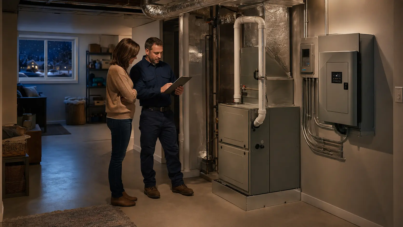
A fuel-burning furnace still needs electricity. The thermostat, control board, draft inducer, ignition system, gas valve, safety switches, circulation blower, and sometimes a condensate pump or powered accessory must complete one coordinated heat call. Backup power succeeds only when that complete sequence works through the final transfer path. Start with the exact heating system, measure its real behavior, and size for the coldest credible outage day rather than a mild afternoon.

A gas or oil furnace can be a manageable backup load, but it is never just a blower.
Many forced-air gas, propane, and oil furnaces can be supported by a correctly sized battery or generator because fuel produces the heat while electricity runs the operating sequence. That does not make the choice automatic. The source must provide the exact voltage, enough starting and continuous output, suitable power quality, compatible neutral and grounding behavior, sufficient cold-day energy, and a safe connection to a normally hardwired circuit.
Electric resistance furnaces and heat pumps are different. Their heating equipment may require large 240-volt output, compressor starting capability, defrost operation, and auxiliary heat management. Do not use a gas-furnace wattage estimate for them. Identify the system first, then have the final design checked against the furnace, thermostat, accessory, backup-source, and transfer-equipment instructions.
Installed battery backup
Strong for a compatible furnace circuit when output, waveform, transfer, runtime, installation environment, and recharge are verified.
Plan the battery routeGenerator backup
Can run heating and other essentials for longer periods, but needs safe outdoor placement, fuel, maintenance, and listed transfer equipment.
Plan the generator routeHybrid battery and generator
Uses battery power for immediate, quiet heat calls and generator or solar recovery when stored energy falls.
Build the hybrid planPortable battery system
Possible only with a permitted connection that powers the complete hardwired furnace safely and passes every operating step.
Check portable suitabilityClassification comes before capacity
“Furnace” can describe very different backup loads
Begin with the equipment that actually produces and distributes heat. A forced-air gas or propane furnace burns fuel and uses electricity for controls, combustion-air movement, ignition, safety proving, and the indoor blower. An oil furnace adds its burner motor and ignition equipment. A boiler may use a burner, controls, circulator pumps, zone valves, relays, and other hydronic devices instead of a large air blower. Each can be a practical selected-circuit backup load, but the whole system must be inventoried.
An electric resistance furnace is fundamentally different because electricity is the heat source. Heating elements can draw many times more power than a combustion furnace blower. A heat pump or ductless mini-split also needs separate treatment because the outdoor compressor, indoor unit, defrost cycle, crankcase heater, controls, and possible auxiliary resistance heat form a larger 120/240-volt system. The homeowner should not infer backup demand from the thermostat screen or from the word “furnace” on a service invoice.
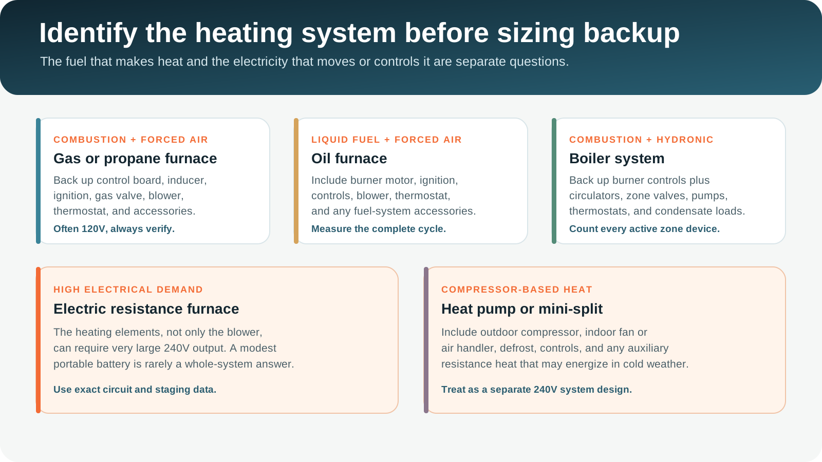
Forced-air furnace
Often a manageable 120V load, subject to exact blower, inducer, controls, thermostat, condensate, accessory, and transfer requirements.
Oil-fired furnace
Count the burner motor and ignition equipment as well as the controls and circulation blower. Startup behavior can differ from gas heat.
Boiler and zones
Inventory circulators, zone valves, relays, burner controls, pumps, thermostats, and any condensate or combustion-air equipment.
Resistance or heat pump
Expect larger 240V demand and more complex staging. Use exact equipment data and a dedicated whole-system design.
Look for the outdoor unit before assuming the home has only a furnace. A dual-fuel system can pair a heat pump with a gas furnace, and the thermostat may decide which source operates. During backup operation, the controls must use an approved mode that matches the available source. Do not defeat lockouts, temperature limits, defrost logic, or safety controls to force a lower-power heat source.
Heat is a sequence
Back up everything required for one safe heat call
A furnace does not simply receive power and spin the main blower. On a typical modern gas furnace, the thermostat requests heat, the control board checks its state, the draft inducer starts, a pressure switch proves draft, ignition begins, the fuel valve opens, flame is proved, and the circulation blower starts after a delay. When the thermostat is satisfied, the burner stops and the blower may continue briefly to move remaining heat. A fault at any stage can stop the cycle or place the control in lockout.
- DemandThermostat
Calls for heat and may need its own power path.
- ControlBoard and safeties
Verify switches, limits, draft, and operating state.
- CombustionInducer and ignition
Establish draft, ignite fuel, and prove flame.
- DistributionBlower or circulator
Move warm air or water through the occupied space.
- AccessoriesPumps and controls
Handle condensate, zones, filtration, and required support.
Accessories are easy to miss. A high-efficiency condensing furnace may discharge condensate to a gravity drain or a powered condensate pump. A humidifier, electronic air cleaner, zone control panel, powered damper, fresh-air controller, communicating thermostat, or home-automation gateway may share the heating sequence. Only devices required for safe heat need outage priority, but bypassing an accessory must be allowed by its documentation and performed correctly.
Some smart thermostats obtain power from the furnace control circuit. Others use batteries, a common wire, or a separate module. A thermostat display that remains lit does not prove the furnace circuit has backup, and a powered furnace does not prove a separately supplied zone panel is alive. Document the source of every control that can prevent heat.
A complete test confirms thermostat demand, draft, ignition, stable flame, blower or circulator operation, warm-air or water delivery, normal shutdown, and successful restart through the final backup connection.
Create one exact system record
Collect labels, circuits, controls, accessories, and operating evidence
Use the furnace model and serial label, installation and service manuals, electrical disconnect, breaker identification, thermostat documentation, accessory labels, and service history. Do not remove energized covers or reach into a furnace cabinet to find information. An HVAC technician and electrician can safely identify conductors, circuit configuration, grounding, neutral behavior, and measured operating demand.
Record the complete heating load
Keep this information with the transfer procedure and emergency contacts. Update it when equipment or controls change.
- Heat typeGas, propane, oil, boiler, electric, heat pump
- Electrical supplyVoltage, phase, breaker, disconnect
- Core equipmentFurnace, blower, burner, circulators
- ControlsThermostat, zones, relays, communicating links
- AccessoriesCondensate, dampers, filters, heat tape
- Measured behaviorStart peak, active watts, duty cycle
Ask for operating data, not a generic wattage
Record the highest credible electrical demand across ignition, inducer start, burner operation, and blower ramp. Note the steady active power after the blower stabilizes, standby demand between calls, the length and frequency of heat calls, and any second stage. For a variable-speed blower, capture the range rather than one moment. For a boiler, note which zones and circulators can overlap.
| Record | Why it matters | Where it may be found | Who should verify |
|---|---|---|---|
| Exact input voltage | The source and transfer path must reproduce the circuit the equipment expects. | Nameplate, manual, breaker, disconnect, wiring documentation. | HVAC technician and electrician. |
| Maximum input or current | Provides a boundary, but does not replace measured cycling and startup data. | Equipment and accessory labels, manufacturer tables. | HVAC technician. |
| Starting or peak demand | Tests whether the source can complete inducer, burner, blower, pump, and control transitions. | Qualified measurement and manufacturer guidance. | Electrician or qualified technician. |
| Active running watts | Forms the base for battery energy and generator continuous-load planning. | Qualified measurement during a complete stable heat call. | Electrician or qualified technician. |
| Cold-day duty cycle | Determines how many hours per day the furnace consumes active power. | Runtime logs, thermostat history, monitoring, or conservative estimate. | Homeowner with HVAC review. |
| Required accessories | A failed condensate pump, zone panel, or powered damper can stop delivered heat. | Equipment survey, manuals, service records. | HVAC technician. |
The breaker rating is not the normal wattage. It protects the circuit and may allow short startup events. Likewise, the blower motor label alone does not include the inducer, controls, ignition, burner equipment, pumps, thermostat, or accessories. Use a complete observed cycle. If a furnace trips breakers, short cycles, locks out, smells unusual, shows corrosion or soot, or has unresolved fault codes, repair the heating system before commissioning backup.
Watts are only one compatibility test
Voltage, waveform, frequency, polarity, neutral, and grounding can affect operation
Electronic furnace controls and flame-sensing systems may respond poorly to an incompatible source or connection even when a wattmeter suggests enough capacity. Follow the furnace and backup-source documentation for voltage, frequency, waveform, grounding, neutral bonding, and transfer configuration. Many homeowners prefer an inverter source with a true sine-wave output for sensitive controls, but the actual requirement belongs to the installed equipment documentation.
Some flame-sensing and control arrangements depend on correct polarity and a stable grounding reference. A portable source that operates lamps and hand tools can still produce a furnace lockout when connected through an unsuitable neutral or grounding arrangement. This is not a reason to modify a generator bond, lift a ground, defeat a safety, reverse conductors, or improvise an adapter. It is a reason for an electrician to coordinate the source, transfer equipment, service grounding, and furnace circuit as one system.
| Compatibility item | Question to answer | Proof before relying on backup |
|---|---|---|
| Voltage | Does the source provide the exact nominal voltage and configuration required? | Documentation, qualified measurement, and complete operating test. |
| Output quality | Are waveform, frequency, voltage regulation, and distortion within equipment limits? | Source specification plus furnace and control requirements. |
| Neutral and ground | Does the source and transfer design handle bonding and switched conductors correctly? | Electrician review of the complete installed architecture. |
| Control compatibility | Do flame sensing, communicating thermostat, zones, relays, and accessories operate normally? | Repeated complete heat calls through final transfer equipment. |
| Fault response | Does the system shut down and recover according to the manual after source or transfer interruption? | Controlled commissioning within manufacturer procedures. |
Pressure switches, limit switches, flame sensing, door interlocks, grounding, venting, and fault controls exist to prevent unsafe operation. Stop, preserve the fault information, and have the source and furnace diagnosed by qualified professionals.
The whole sequence must pass
Prove inducer, ignition, flame sensing, blower start, and normal shutdown
The largest electrical event is not always the first event. The inducer may start, ignition equipment may energize, and the main blower may begin later. An ECM variable-speed blower can ramp differently from a permanent-split-capacitor motor. An oil burner has its own motor and ignition sequence. A boiler may start a circulator or multiple zone devices. Capture the highest demand across the complete call and repeat the test enough times to catch normal variation.
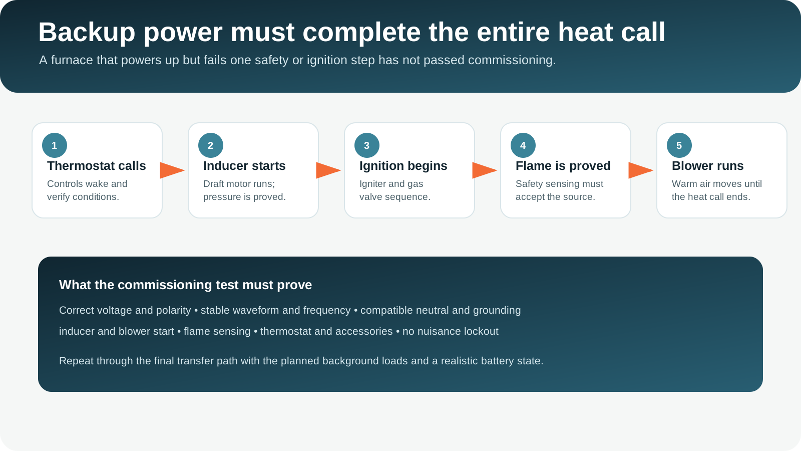
- 1Start from the final architecture
Test through the installed battery, generator inlet, transfer switch, critical-load panel, or other approved connection, not a temporary bench arrangement.
- 2Use realistic background loads
Keep the refrigerator, internet equipment, selected lights, pumps, and other loads that will remain active during an outage.
- 3Observe the complete heat call
Confirm thermostat demand, inducer, ignition, stable flame, blower or circulator, delivered heat, normal shutdown, and post-purge.
- 4Repeat at a realistic source condition
For a battery, include a reduced state of charge and approved cold-weather conditions. For a generator, test after warm-up and with planned fuel and load management.
- 5Record faults and recovery
Document any voltage dip, overload, lockout, thermostat reboot, control reset, nuisance trip, abnormal sound, or restart delay.
A source that succeeds once with no other load is not necessarily ready for a winter outage. The highest furnace transition can overlap with a refrigerator compressor, sump pump, well pump, or other motor. The inverter or generator must support that combined moment or the control strategy must prevent the overlap.
Separate power from energy
Measure the hardest instant and the full cold-day consumption
Output sizing asks whether the source can run the furnace right now. Energy sizing asks how long it can continue. First record the highest credible instantaneous demand during the complete sequence. Add the running power of loads that may overlap. Then compare the result with the source's continuous output, short-duration overload behavior, circuit voltage, and any manufacturer motor-start guidance.
Energy requires active watts and active hours. If a furnace draws 500 watts while heating and runs 40 percent of a 24-hour day, its active energy is 4,800 watt-hours. That does not include standby consumption, condensate equipment, thermostat or zone controls supplied separately, other home loads, inverter loss, reserve, battery temperature effects, or aging.
A plug-in energy meter is appropriate only for equipment that is factory cord-and-plug connected and remains within the meter's ratings. Most furnaces are hardwired. Do not convert the circuit, open energized equipment, or expose conductors to obtain a reading. A qualified professional can use suitable instruments and follow safe procedures.
Duty cycle is the most uncertain input. A furnace that runs 20 percent of the time on a mild day may run much longer during severe wind, a deep temperature drop, recovery from setback, a dirty-filter condition, or building heat loss. Variable-capacity equipment may run for long periods at lower power. Use runtime history near the intended design temperature where available, then add a prudent planning margin and an alternative if weather exceeds the model.
Use the calculator only after the complete cycle is measured
Model the furnace with every other essential load, then test startup and delivered heat through the final connection.
Design for the difficult day
Turn cold-weather duty cycle into a 24-hour battery target
The calculation starts with measured active power, not furnace input heat or fuel consumption. A gas furnace rated in BTU per hour does not consume that number of electrical watts. The blower, inducer, ignition, controls, and accessories determine electrical demand. A high-efficiency blower may use less power at one airflow setting and more at another, so record the actual heating mode.
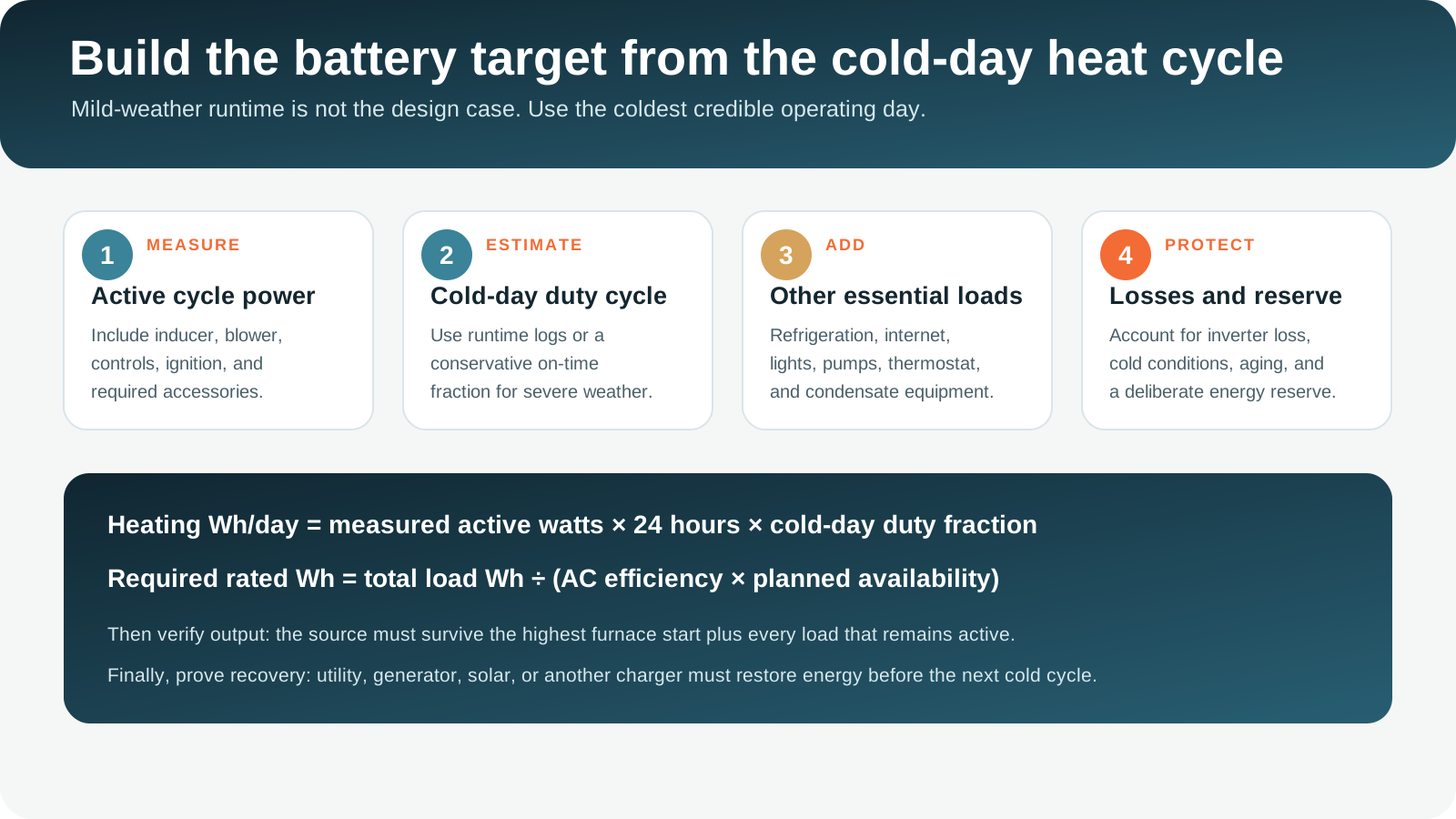
Example energy calculation
A measured furnace uses 420 W during a stable heat call and is expected to run 55 percent of a severe 24-hour day. Heating energy is 420 × 24 × 0.55 = 5,544 Wh. Add 120 Wh for controls and accessories plus 1,700 Wh for selected refrigeration, communications, lighting, and monitoring. Total load energy is 7,364 Wh.
Translate to rated battery capacity
If the planning model delivers 90 percent AC efficiency and keeps 10 percent of rated energy unavailable as reserve, the combined factor is 0.90 × 0.90 = 0.81. Required rated capacity is 7,364 ÷ 0.81 = about 9,091 Wh. Installation temperature, system limits, aging, source overhead, and recharge can justify more margin.
This example is transparent, not a universal furnace estimate. Replace every input with the installed system's measured values. If the furnace has two stages, variable airflow, or a communicating control, model the credible cold-day mix. If several boiler zones can call together, include overlapping circulators and zone controls. If a heat pump can energize auxiliary resistance heat, model and manage that load explicitly rather than assuming compressor-only energy.
Recharge changes the required storage. A battery that must bridge only six quiet nighttime hours can be much smaller than one expected to carry two sunless days. Generator charging must remain within the battery system's accepted AC input, the generator's continuous output, and the transfer design. Solar recovery depends on season, snow, shading, weather, array orientation, controller limits, and the short winter day. Do not treat panel nameplate watts as guaranteed daily energy.
Choose the architecture, not only the device
Compare installed battery, portable battery, generator, and hybrid routes
| Route | Best fit | Main strengths | Critical checks | Long-outage boundary |
|---|---|---|---|---|
| Installed home battery | Automatic furnace and essential-circuit coverage. | Fast transfer, quiet operation, indoor load management, no onsite combustion during use. | Output, surge, 120/240V architecture, neutral and ground, usable energy, approved location, cold behavior, recharge. | Finite stored energy requires grid, solar, generator, or another recovery path. |
| Portable battery system | Smaller compatible furnace with an approved, planned connection. | Portable, quiet, no engine exhaust during discharge. | Hardwired-circuit connection, output, waveform, bonding, furnace controls, cable and inlet ratings, runtime. | Connection and recharge are often the limiting steps. |
| Portable generator | Extended outage with available fuel and a trained operator. | Can support heating and recharge when fuel is managed. | Outdoor placement, CO, weather protection, transfer isolation, voltage, motor starts, neutral and ground, maintenance. | Fuel, noise, refueling, weather, engine reliability, and operator availability. |
| Standby generator | Automatic longer-duration heat and broader home coverage. | Automatic start and strong sustained output when fuel and installation are suitable. | Load sizing, fuel capacity, placement, exhaust, service, transfer, cold starting, exercise, local requirements. | Fuel interruption or mechanical failure still requires a fallback. |
| Hybrid system | Quiet immediate heat with planned recovery for multi-day outages. | Battery carries short cycles; generator runs in efficient windows; solar may add recovery. | Charging compatibility, control thresholds, transfer architecture, source isolation, reserve, failure modes. | More controls require careful commissioning and a simple manual fallback. |
Installed battery route
An installed battery can place the furnace on an essential-load panel or managed whole-home system. It should transfer quickly enough for the controls, provide the correct circuit architecture, support startup with background loads, and retain enough cold-day energy. Confirm whether the thermostat, zone controls, condensate pump, and other required accessories are on the backed-up side. Locate the battery only where its listing, manufacturer instructions, fire and building requirements, and local authority allow.
Portable battery route
The difficult part is often the connection, not the wattage. A normally hardwired furnace should not be casually rewired to accept an extension cord. Some jurisdictions and equipment configurations may permit a listed furnace transfer device or a professionally designed connection, while others require a panel-based transfer method. Have the exact design approved and installed as required. The source must still pass flame sensing, controls, blower start, and the complete heat call.
Generator route
Size a generator around the highest furnace event plus the loads that remain active, not the sum of every appliance label. Stage a well pump, sump pump, refrigerator, freezer, and furnace where practical. Use only an approved transfer arrangement that isolates utility power. Portable generators belong outdoors at least 20 feet from the home according to current CPSC guidance, with exhaust directed away from the home and all building openings. Never use one in a basement, garage, shed, porch, or carport.
Hybrid route
A hybrid plan can reserve the battery for automatic heat calls, communications, and controls while a generator runs during scheduled recovery windows. This reduces overnight noise and avoids running an engine at a very light load for every short thermostat call. The generator-to-battery charging path must be explicitly supported, and controls must prevent conflicting sources. Set reserve thresholds around weather, occupants, fuel, and the minimum energy needed to restart heat.
Model recovery before choosing storage
Battery capacity, generator fuel, solar seasonality, recharge rate, and the next cold night belong in one operating plan.
A hardwired load needs a designed path
Use listed transfer equipment and keep utility power isolated
Most central furnaces are hardwired through a dedicated branch circuit and service switch. Safe backup can be provided through a transfer switch, critical-load panel, whole-home battery system, generator interlock arrangement where permitted and correctly installed, or a listed furnace-specific transfer device accepted for the application. The correct method depends on the service, source, furnace, local code, listing, neutral design, overcurrent protection, and authority having jurisdiction.
Never connect a generator to a receptacle with a double-male cord. Never energize a panel while the utility source remains connected. Never remove a furnace service switch, door safety, ground, or protective conductor to make a temporary setup work. OSHA warns that a generator connected to a structure without proper transfer isolation can backfeed utility wiring and endanger workers and others.
Critical-load panel
Places the furnace and chosen essentials on a backed-up panel with clear capacity and load priority.
Whole-home transfer
Backs up a broader panel while controls shed large electric heating, cooking, EV, and cooling loads.
Listed furnace transfer
May serve a specific compatible furnace where accepted, correctly installed, and coordinated with the source.
Label the operating sequence at the transfer point. A manual plan should state which loads to turn off, how to verify utility isolation, how to connect and start the source, when to enable the furnace, how to confirm a normal heat call, and how to return to utility power. An automatic system should still have a documented manual shutdown and fault response.
Protect the backup source from the installation environment. Batteries have approved temperature and location limits. A furnace room can have service-clearance, combustion-air, heat, ignition-source, and fire-separation requirements. A battery, fuel can, extension cord, or unrelated storage item should never obstruct furnace access, combustion air, venting, disconnects, or the electrical working space.
Transparent examples
Three profiles show why measurement and duty cycle matter
These examples are planning exercises, not appliance ratings or purchase recommendations. They assume a combined 90 percent AC conversion efficiency and 90 percent planned availability after reserve, producing a 0.81 delivery factor. They do not replace manufacturer limits, installation derating, battery temperature effects, aging, wiring loss, source overhead, or commissioning.
Efficient gas furnace, managed night
- Measured active furnace demand: 260 W
- Highest furnace event: 520 W
- Severe-night duty cycle: 50%
- Planning window: 12 hours
- Other essential energy: 900 Wh
- Heating energy
- 1,560 Wh
- Total load energy
- 2,460 Wh
- Rated capacity model
- 3,037 Wh
260 W × 12 h × 0.50 = 1,560 Wh. Add 900 Wh, then divide 2,460 by 0.81. Output must also survive the 520 W furnace event plus active background loads.
Gas furnace, severe full day
- Measured active furnace demand: 480 W
- Highest furnace event: 1,050 W
- Cold-day duty cycle: 60%
- Planning window: 24 hours
- Other essential energy: 2,000 Wh
- Heating energy
- 6,912 Wh
- Total load energy
- 8,912 Wh
- Rated capacity model
- 11,002 Wh
480 W × 24 h × 0.60 = 6,912 Wh. Add 2,000 Wh, then divide by 0.81. A long outage needs a credible recharge path, not only more stored energy.
Oil furnace and essential circuits
- Measured active heating demand: 760 W
- Highest combined furnace event: 1,700 W
- Cold-day duty cycle: 45%
- Planning window: 24 hours
- Other essential energy: 2,400 Wh
- Heating energy
- 8,208 Wh
- Total load energy
- 10,608 Wh
- Rated capacity model
- 13,096 Wh
760 W × 24 h × 0.45 = 8,208 Wh. Add 2,400 Wh, then divide by 0.81. Generator or hybrid recovery may be more practical for repeated severe days.
The output check is separate. In Profile 2, suppose a refrigerator is using 180 W and a sump pump may start while the furnace is active. The source must support the real overlap or the load-management plan must prevent it. Do not assume that a large watt-hour number guarantees adequate inverter output, motor-start response, or correct voltage.
The building is part of the backup system
Plan temperature, pipes, fuel, ventilation, occupants, and relocation together
Cold-weather backup protects people first, then plumbing and property. The time available after heat loss depends on outdoor temperature, wind, insulation, air leakage, thermal mass, sun, building shape, exposed pipes, crawlspaces, attic plumbing, and neighboring conditioned space. A single indoor thermostat can miss a cold utility room, exterior-wall pipe, remote bathroom, or vacant zone.
Place temperature sensors in the occupied area and known freeze-risk locations. Choose devices that remain useful during internet and utility failure, and keep local alarms where needed. Do not rely on cloud access as the only warning. Record who will respond if the system faults while the home is empty.
Health and safe warmth
Prioritize infants, older adults, medical needs, limited mobility, and anyone unable to recognize or report cold stress.
Cold spots and water
Monitor vulnerable pipes, know the shutoff, and use a plumber-approved response if heat cannot be maintained.
Two supplies may matter
A fuel-burning furnace needs both electrical backup and adequate heating fuel. Generator fuel is a separate dependency.
Relocation threshold
Set a clear point for leaving safely rather than waiting for the battery, fuel, indoor temperature, or road access to become critical.
Reduce demand before an outage by maintaining filters, sealing major air leaks, servicing heating equipment, protecting exposed plumbing, and understanding the home's heat-loss pattern. During an outage, close unused rooms only when doing so does not create a pipe, ventilation, combustion-air, or occupant-safety problem. Use blankets and layered clothing. Follow Ready.gov and local emergency guidance for safe warming locations and severe-weather decisions.
Do not use an oven, grill, camp stove, charcoal device, or unvented combustion appliance to heat the home. Portable heaters must be used only as listed and with the required clearance and electrical capacity. A portable electric heater can also consume far more battery energy than a combustion furnace blower, so adding one may collapse the runtime model.
Commission before the storm
Test transfer, complete heat calls, source reserve, shutdown, and utility return
Coordinate the furnace technician, electrician, battery installer, or generator provider where responsibilities overlap. The test should follow every equipment manual and local requirement. Schedule it when a safe fallback is available, not during the first severe outage.
- 1Inspect the heating system
Confirm service, filters, venting, combustion air, condensate path, fuel supply, thermostat, faults, alarms, and every required accessory.
- 2Inspect the backup architecture
Confirm source rating, battery location, generator placement, inlet, transfer, labels, conductors, protection, grounding, neutral design, and load management.
- 3Simulate utility loss safely
Use the approved commissioning procedure. Verify transfer without exposing conductors or bypassing interlocks and safeties.
- 4Run repeated complete heat calls
Observe demand, inducer, ignition, stable flame, blower or circulators, delivered heat, normal shutdown, restart, and accessory operation.
- 5Add planned background loads
Test the refrigerator, pumps, communications, lights, and controls that will share the source. Confirm load-management priorities.
- 6Verify endurance and recovery
Run a representative period, compare measured energy with the model, recharge or refuel safely, and confirm the next heat call.
- 7Return to utility and document
Verify normal transfer, reset only according to instructions, record results, photograph labels, and keep the operating card accessible.
Repeat the backup test on a schedule supported by the equipment manufacturers and after meaningful changes to the furnace, thermostat, electrical service, generator, battery, transfer equipment, fuel system, or essential-load plan. Replace recalled or expired safety equipment. Test smoke and carbon-monoxide alarms according to their instructions.
More capacity does not fix every fault
Plan for electrical, control, combustion, fuel, and distribution failures
| Observed problem | Possible category | Safe planning response | Do not do |
|---|---|---|---|
| Furnace has no power | Transfer, breaker, disconnect, wiring, source, or depleted battery. | Follow the documented source and transfer checks; use a qualified professional if the cause is not obvious and safe. | Do not open energized equipment or bypass the service switch. |
| Controls power but burner locks out | Power quality, polarity, grounding, flame sensing, ignition, fuel, venting, or furnace fault. | Preserve the fault code and stop for HVAC and electrical diagnosis. | Do not defeat flame sensing, pressure switches, limits, or grounding. |
| Source trips when blower starts | Startup overload, voltage drop, shared motor overlap, wiring, or source limit. | Review measured peak, load management, conductors, output limits, and source condition. | Do not increase breakers or bypass overload protection. |
| Burner operates but rooms stay cold | Blower, circulator, zones, dampers, filter, duct, thermostat, or distribution fault. | Shut down if required and have the complete delivery system checked. | Do not assume combustion alone means safe delivered heat. |
| Battery drains much faster than modeled | Higher duty cycle, hidden accessory, cold battery, aging, inverter overhead, or other loads. | Measure actual energy, reduce discretionary loads, restore energy, and use the fallback threshold. | Do not run below required reserve when occupants or pipes are at risk. |
| CO alarm sounds or combustion seems abnormal | Potential life-safety emergency. | Move to fresh air and contact emergency services as directed by the alarm and authorities. | Do not ignore, silence, or repeatedly reset the alarm to keep heat operating. |
Build a fallback that does not depend on the same failure point. A second battery on the same failed inverter is not independent. A generator that cannot connect through the transfer equipment is not recovery. A second thermostat does not fix failed venting. Useful layers can include a safe warming location, monitored temperatures, a second approved recovery source, trained operators, service contacts, fuel, spare alarm batteries, and a planned plumbing response.
Non-negotiable boundaries
Protect people from backfeed, carbon monoxide, fire, fuel, and unsafe heat
A power outage does not suspend furnace, generator, electrical, fuel, or combustion rules. Use qualified professionals where required. Follow the current equipment manuals and the local authority having jurisdiction.
Use listed transfer equipment. Never energize house wiring through an improvised cord or while the utility source can remain connected.
Operate portable generators outdoors only, at least 20 feet from the home, with exhaust directed away from the home and every opening.
Keep venting, combustion air, condensate, clearances, doors, limits, flame sensing, and service access intact.
Install and maintain working CO alarms as required. Treat an alarm as an emergency, not a nuisance to silence.
Store and use fuel according to law and manufacturer instructions. Shut down and cool portable generators before refueling.
Use listed equipment in approved locations with required clearances, protection, ventilation, temperature limits, and service access.
Have fuel-burning heating equipment inspected and maintained according to its manufacturer and local requirements. Keep furnace vents and outdoor intake or exhaust terminations clear as instructed. Do not block combustion air to conserve heat. Do not place storage against the furnace or backup equipment. Do not operate a portable generator in a garage even with the door open.
Installer handoff
A furnace backup plan is ready when every item is documented and tested
- Heating type confirmedGas, propane, oil, boiler, electric resistance, heat pump, dual fuel, and distribution equipment are correctly identified.
- Complete load inventoriedThermostat, controls, inducer, ignition, burner, blower, circulators, zones, condensate, and required accessories are included.
- Electrical supply verifiedVoltage, phase, circuit, breaker, disconnect, conductor, neutral, ground, and source architecture are recorded.
- Startup measuredThe highest event across the complete heat call is known and tested with realistic background loads.
- Cold-day energy modeledActive watts, severe-weather duty cycle, standby loads, accessories, other essentials, losses, temperature, aging, and reserve are visible.
- Transfer is safeUtility and backup cannot energize the circuit together, equipment is listed for the application, and every operator understands the sequence.
- Recovery is credibleBattery recharge, generator fuel, solar seasonality, operating windows, reserve thresholds, and the next cold night are addressed.
- Combustion remains intactVenting, intake, condensate, clearances, alarms, fuel, service access, and all furnace safeties remain functional.
- Freeze risks are mappedOccupied zones, remote rooms, plumbing, crawlspaces, sensors, shutoff, and relocation thresholds are documented.
- Complete sequence passesTransfer, thermostat demand, ignition, stable heat, blower or circulators, shutdown, restart, recovery, and utility return are tested.
Common questions
Furnace backup power questions
Can a portable power station run a gas furnace?
Some can, but only when output, energy, power quality, neutral and grounding behavior, and the connection method are compatible with the complete installed furnace. Most furnaces are hardwired, so a safe listed transfer path is often the decisive issue. Test thermostat, inducer, ignition, flame sensing, blower, accessories, shutdown, and restart.
How many watts does a furnace use?
There is no reliable universal number. Blower type and speed, inducer, ignition, burner equipment, controls, thermostat, accessories, stages, ducts, and system condition all matter. Use manufacturer documentation and qualified measurements across a complete heat call.
How long will a battery run a furnace?
Multiply measured active watts by active hours, add controls, accessories, and other essential loads, then account for inverter loss, planned reserve, temperature, and aging. The battery must also pass the highest startup overlap at the remaining state of charge.
Does a gas furnace work when the power is out?
Usually not by itself. Modern gas furnaces generally need electricity for controls, draft inducer, ignition, safety proving, gas valve operation, and the circulation blower. A standing fuel supply does not replace electrical backup.
Can I plug a hardwired furnace into an extension cord?
Do not improvise this conversion. The acceptable connection depends on the furnace, circuit, source, listing, transfer equipment, local code, neutral and grounding design, and authority having jurisdiction. Use a qualified electrician and HVAC professional.
Why does the furnace lock out on a generator that has enough watts?
Possible causes include voltage or frequency behavior, waveform, polarity, neutral and grounding configuration, voltage drop, flame sensing, control compatibility, fuel, venting, or an unrelated furnace fault. Preserve the fault code and have both the electrical source and furnace diagnosed. Do not bypass a safety.
Is an electric furnace practical on battery backup?
Electric resistance heating can require very large 240V output and substantial daily energy. A whole-home battery or generator design may support it when specifically engineered, but a modest portable battery is generally a poor assumption. Consider essential-load management and a safe cold-weather fallback.
Should I include a heat pump in the furnace calculation?
Treat the heat pump as its own complete system. Include outdoor compressor, indoor air handler or fan, defrost, controls, heaters, and any auxiliary resistance heat that may energize. A dual-fuel thermostat and changeover controls must also operate in an approved backup mode.
Can I run a portable generator in the garage if the door is open?
No. Current CPSC guidance says portable generators belong outdoors only, at least 20 feet from the home, with exhaust directed away from the home and other building openings. A garage, basement, shed, porch, or carport is not a safe operating location.
Identify the system, prove the entire heat call, and size for the cold day
Record every powered part of the heating system, verify voltage and source compatibility, measure the complete startup and active cycle, and calculate energy from a credible cold-weather duty cycle. Then use listed transfer equipment, protect combustion and carbon-monoxide safety, test the system with shared loads, and define recovery and relocation before stored energy or fuel becomes critical.
Technical and safety sources
- U.S. Department of Energy: furnace electrical energy use, including blower, draft inducer, ignitor, and auxiliary equipment
- U.S. Department of Energy: Energy Saver guide for furnaces, boilers, heat pumps, maintenance, and thermostat operation
- U.S. Consumer Product Safety Commission: 2026 generator, furnace, and space-heater winter safety guidance
- U.S. Consumer Product Safety Commission: 2026 winter-outage carbon-monoxide and fire guidance
- Occupational Safety and Health Administration: generator transfer and backfeed safety
- Ready.gov: winter-storm and power-outage preparedness
- Ready.gov: 2026 Stay Safe and Warm toolkit
Reviewed July 26, 2026. The furnace, thermostat, accessory, battery, generator, transfer, fuel, alarm, and building documentation, plus local electrical, mechanical, fuel-gas, fire, building, and permitting requirements, control the final design. Use qualified HVAC and electrical professionals where required.